1969 (soon to be) 2000ti TURBO INJECTION!

Over the last few days i've been working on the rover pretty full on as iv had thde week off so after i got the engine out i strated taking the engine mounts off which took me twice as long as it did to get the engine out but there done now
S1032756.jpg

S1032757.jpg

and then i tried the new engine in with the turbo in its roiginal position
S1032765.jpg

the turbo just catches the upright where the bottom suspension arm joins the body so i cant modify that bit too easily so i think i will have to move the turbo which i was trying to avoid but the clearence issues mean that the engine wont sit straight so it will have to be moved.
S1032767.jpg

S1032766.jpg

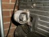
also the oil filter clearance which i had been told would be an issue was quite bad with the turbo in place
S1032773.jpg

and the engine sat too high up to clear the bonnet
S1032775.jpg

but then i took the turbo off and went in for another go with a little more success,
the removal of the turbo ment tha the engine could be placed further back and this reduced the contact between the x-member and oil filter
S1032776.jpg

and let the engine sit lower and more inline
S1032781.jpg

the tensioner pully is close to the crossmember but i think it will clear without too much hassle
S1032780.jpg

so still need the bits to connect everything together but im getting there will move the turbo up to the top of the engine and try and work some more stuff out
 
S1032775.jpg


Looking at that picture the first thing that springs to mind is an MGC bonnet bulge :LOL:

How much space is there between the engine block and the anti roll bar and heater? If it's just the heater in the way, and you have enough clearance between the block and the anti roll bar to go back further, you could cut a section out of the heater to slot the engine inside and hopefully drop the filter behind the crossmember?

The next issue I see are the engine mounts, as they appear to be as far away from the chassis rails and crossmember as you could possibly get. I'm guessing the bosses on the front of the block are sitting at a similar height to the chassis rails, not exactly an ideal situation to securely mount an engine I believe. If you get a sherpa sump, it could be possible to make a removable secondary crossmember that runs behind the front crossmember bolted to the chassis rails or bumper irons each side running underneath the engine, and make the mounts up to suit?

Of course this all depends on how the gearbox affects the placement of the engine in the 'bay. You're definately making good progress :D
 
S1032778.jpg

I've got about 4inches but i was worried about the gearbox as i dont want to have to get a prop shortened and have to shorten the remote like you have as it seems expensive and time consuming.
The main problem is the sump and oil filter at the moment if i fit the engine far enough forward to use the cross member for mounts the sump catches it and sends the engine skywards, i quite like the idea of the 2nd cross member but the sump would catch this too and i rang the man about the perkins prima and for the mounts and aux he want the shirt of my back so i will keep looking.

in terms of bonnet bulges this is what id do (not going to theres no need now)
b1852.jpg
 
If the engine moved those 4" back would it all clear then? Maybe another propshaft from either an auto 4 pot or manual/auto v8 would fit better? I'll measure the total length of my box sometime possibly tomorrow for you, and there is always the sherpa short remote that fits the lt77, although that maybe a little too short :LOL:

I think the 600 was the only rover to have an alloy sump, so finding a steel sump and pick up from something else and cutting & shutting that could work, but nothing compares to physically having the sherpa bits infront of you to see how it would all slot together.
 
yes im pretty sure it would i will se tommorow and try pop a gearbox up in the tunnel to see where it should be.


right I looked at moving the engine back further but it catches the heater on the breather pipe off the rocker cover.
placed the turbo where i want it, i with need a u shape pipe off the manifold and spin the centre of the turbo round to get the oil feed at the top and the return at the bottom.
S1032782.jpg

S1032784.jpg

and then started to look at engine mounts,i think that i will mount them on the chassis rail facing down at an angle towards the engine, i have made some cardboard templates.
S1032788.jpg

S1032787.jpg

the metal mounts will also be braced from underneath.
 
just got in from putting the 4 speed box back in and making sure it all lines up (and it does suprisingly)
S1032791.jpg

then i wipped the engine back out and adjusted the cross member i tapped it back under the ideler pully to get another 10mm clearance
S1032790.jpg

and then cut around the oil filter which let the engine sit even better but still need to cut another half inch so it dosent catch
S1032789.jpg
 
The engine sits almost exactly as I imagined it would from my measurements, with the rocker covers almost tucking under the ledge of the heater and the position where the oil filter would foul the crossmember. Luckily the filter looks like it is just inboard of the internal structure for the front suspension arm so should be a simple job to weld a plate over the hole you've cut.

I've measured my sherpa gearbox and it is 26.25" ish from the rear face of the block to the output flange, and the gearlever sits 30.75" ish from the rear face of the block. My concern over the engine mounts as you have made in cardboard is that they sit a long way from the chassis rail and go down, to me it doesn't look like an ideal situation considering the torque loads and weight of the engine, but again it's difficult to say without physically seeing exactly how you've made them and how they would attach to the rails. If they wrap around the rails top and bottom they should be OK, but it is still a lot of leverage acting on the rails.

Here's a side on pic of the stock sherpa sump:

100_2508.jpg


If it were me, going by you're photos and my measurements, I would make a secondary crossmember, about 1" deep and 2.5" wide or thereabouts, following the profile of the original crossmember under the sump with the mounts sitting on top of it and bolted securely to the chassis rails, preferably once they've been sleeved for strength.

I'm intrigued by what engine mounts you plan on using looking at you're templates, not standard rover I'm guessing 8)
 
well i was going to make or get simple cylinder style bushes inside a metal tube that would be welded to an engine mount and then bolted to the block if you get what i mean. also they would be braced underneath to the bottom of the rail if i then connect both mounts (body side) together with an inch box section crossmember as you suggested on rr like shown in this little drawing
S1032794.jpg
 
^ Gotcha thats a good idea :D , how about using the top hat bushes from the front suspension off the bulkhead? I've kept a few good ones aside that I intend to use myself, and they're a standard rover part to the p6.
 
im unsure of what bushes you mean, i will have to look at different bushes and see what i find i dont know what cars had the bushes that i was planning on using it just seemed the easiest way of doing it.
this is the bush how i would mount it
bush.jpg
 
Hi, a ready made item exists and it is a Rover part!!


Guys building off road specials used to use them as they were strong, however
there is not much give in the bush. So you may find that it transmits a lot of
engine noise. which is OK in an offroader but maybe unacceptable in a road
going car. Keep up the good work!

Colin

P.S. forgot to say it is a Land rover series 3 rear spring rear hanger bracket.
 

Attachments

  • hanger bracket.jpeg
    hanger bracket.jpeg
    2.3 KB · Views: 930
here comes the point where i realise ive been over complicating the the engine mounts like a bit of an idiot.
when i could just go straight for the 2nd crossmember with v8 type mounts attached as sowen suggested a long time ago :oops:
 
This is the power of internet forums, everyone has a little idea, throws it in the pot and out comes a nice big plan of action :D

Is there enough room to copy the v8 brackets welded to the front crossmember or does the engine sit too low and far back for that? Also, is there a way to add a stabiliser bracket high up like the v8 has on the side?

I'm all for finding an alternative to the rubber bobbin style engine mount as used on the v8, as I've broken enough of them on my land rover. I was going to use chassis bushes as Colin has suggested for engine mounts on it when I put the bigger v8 in place, and anyway, a properly balanced and serviced engine should not vibrate. How many people here have sat an engine on the floor unsupported and fired it up? I have and they don't go off dancing down the street :LOL:

The top hat bushes I suggested are the outer pivot link bushes on the bulkhead, you'll have them on your spares car :D

100_2224.jpg
 
yes the engine is too far back to use the v8 mounts on my crossmember but i ment using them on the 2nd crossmember but at a risk of over complicating again i could use the cylindrical type bushes attched to the 2nd crossmember
S1032798.jpg

nd i found a bush like the ones i was planning on using
S1032797.jpg

and i haddent thoughtabout the engine steady bar but it should'nt be too difficult using the original t16 engine mount on the front and 2000 steady bar.
S1032796.jpg

yes that mount is overkill but you get the idea.
also note that the oil filter hole now fits.
 
That mount you have there looks like a steady bar, did it come with the t16? It looks like it would do the job, possibly much better than bobbins in my opinion. The top steady bar I would consider essential, as you're fitting an engine that could produce more torque than the v8 which had it fitted as standard.

Looking at the front mount that you've layed the p6 steady bar against, it looks like the fwd t16 is designed to hang from the top with a steady bar underneath the rear, definately overkill, and being on show you could do something creative if you want 8)
 
the mount thats laid on the slam panel was attached to the mount on the front of the engine when i bought it but the it was going to go in a 205gti so im not sure whats standard or not and whats supposed to be there or not. if im going to use that sort of bush they will need to be slightly smaller to fit how i want them.
turbo question time now:
im struggeling with the big circlip on the back of the inlet side of the turbo and a couple of bolts on the exhaust side but if i can get them off would i be able to spin the centre round to get the oil suppy at the top and return at the bottom and then what about where the down pipe (or currently up pipe) attaches?


update;
made the crossmember out of cardboard and tried it on but it sits far too low this pic has a bit of box section where the crossmember would end up.
S1032799.jpg

so i may go for a different option of having the cross member up-side-down like so
S1032800.jpg

using the original 620 engine mount and a steady bar at the bottom but i would have to make the crossmember look quite nice and easily detachable.
i got the bolts loose on the back of the turbo but still cant spin the centre round, any ideas?
this is my last day off for awhile so progress with slow quite dramaticly. :(
 
Before you get too carried away working with that 600 front mount, have a look at the one used in an 800, it's a much simpler design with just one big mount rubber.

I did a quick google but couldn't find a picture, I'll take one later and post it.
 
the top one or the original one? if you mean the original one yes it does. i wasn't planning on using the ally bit i was going to make my own steel mount.
I found one
7.jpg

that looks like the easiest method.
 
That's very similar to the 800 one.


Although I'm not sure you need anything on the front anyway, most rwd engine setups don't have anything like that, the Rover seems quite unusual with the stabiliser rods.
 

Attachments

  • mount.jpg
    mount.jpg
    418.9 KB · Views: 852
Back
Top