Top end rebuild

arthuy said:
I have not long completed a top end rebuild on my v8.

I set out to replace the worn parts and ended up doing the full lot. rockers, rocker shaft, pedestals, rods, camshaft, followers, jp timing set.

Hi Colin, As inevitably 2008 turns to 2009, inevitably this is a project that will expand to the farthest reaches of my wallet. But as you say, I will be glad I did it! And so many smiles/frustrations along the way! :) :evil:

For instance....
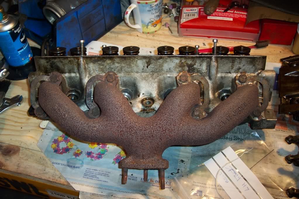
Seen the state of those studs?


Copious Plus Gas & heat & talking nicely...Will they move? Will the b*****y! Drilling out to look forward to...

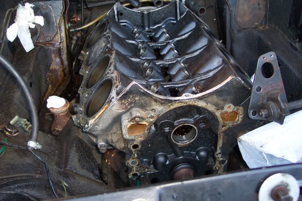
And...no wonder she didn't like sitting in traffic. Not much coolant been flowing through here....


What a forgiving engine!

Anyway...Happy Hogmanay!
 

Attachments

  • 100_1725a.jpg
    100_1725a.jpg
    114.2 KB · Views: 1,570
Hello Stan,

Happy New Year!

Just looking at your photo of the coolant sludge resting in the cylinder head channel. The coolant from the cylinder head actually does not enter the inlet manifold at that point, as there is no coolant pathway within the manifold at this location.

As the heads are not sided, there are coolant channels at both ends, but the manifold design prevents coolant from exiting the head at the rear, thus ensuring that coolant flows right through each head prior to exiting at the the inside front, only entering the inlet manifold from each head at this location.

Ron.
 
SydneyRoverP6B said:
Hello Stan,

Happy New Year!

Just looking at your photo of the coolant sludge resting in the cylinder head channel. The coolant from the cylinder head actually does not enter the inlet manifold at that point, as there is no coolant pathway within the manifold at this location.

As the heads are not sided, there are coolant channels at both ends, but the manifold design prevents coolant from exiting the head at the rear, thus ensuring that coolant flows right through each head prior to exiting at the the inside front, only entering the inlet manifold from each head at this location.

Ron.

Ah..thanks Ron. And Happy New Year to you! I think the sludge is indicative of infrequent coolant changes in this engine's past though. When I bought the car earlier this (no..last! :D ) year I was amazed at the amount of crud that came out of the engine & radiator when I flushed it.

Cheers,
 
DaveHerns said:
Keep us informed
You may persuade me to do the same job on mine !

I will indeed Dave! In fact, this thread may be better placed in Members Projects as I'll be posting pics throughout the job...which, given all the other tasks in life, will run for quite a while!

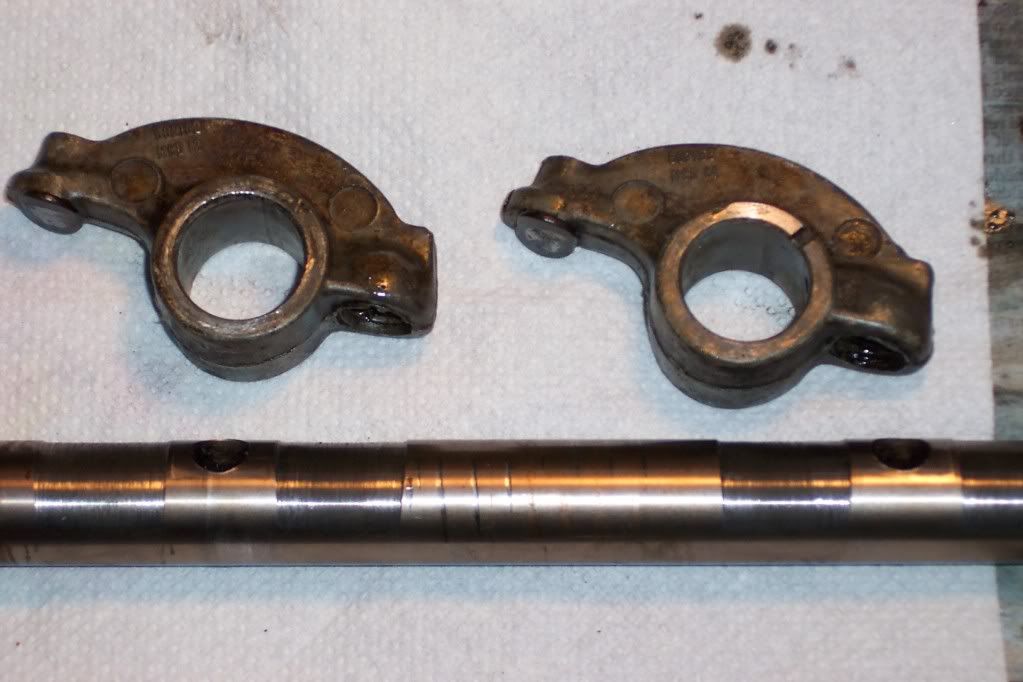
OK..took the RH rockershaft assembly apart...

.015" - .020" wear on the underside of the shaft!


And with my anorak on and zipped..the rocker arms are date-stamped 1972 but are numbered 602162 & 602163, whereas the Parts Book gives 602153 & 602154? Or are the former numbers just diecasting numbers? Just interested if anyone can shed any light.

I've got a pair of assemblies and pushrods from a 4.6 Range Rover that was being broken, and they look pretty good but I may go for new shafts anyway.
 
SydneyRoverP6B said:
Using a standard 3.9 camshaft will see only a 5 to 8 BHP increase over the standard 3.5 camshaft surplied for carburettor engines, according to V8 Tuner.

http://www.v8tuner.co.uk/product.php?id=62


Ron.

:?:

That figure on it's own is pretty much meaningless. 5 to 8 BHP increase where? I'd accept that in terms of maximum power that's probably about right, but that was never the objective. IIRC the idea was to make the engine power more suitable for use in the Landie, where low down grunt is more important than outright power, and to do this without causing problems by using a different profile and extra lift, the timing was altered, giving as I said earlier the big boost in the midrange, without losses elsewhere, (and as an incidental benefit to that a smaller increase at the top end if you let it rev out,) but that wasn't the thinking behind the change in the first place. Fitting it in the 3.5 gives the same benefits but with slightly less capacity to play with.

As the V8 isn't a particularly high revving engine without serious mods I'd happily accept the small nominal increase for the hike in useable power.
 
harveyp6 said:
SydneyRoverP6B said:
Using a standard 3.9 camshaft will see only a 5 to 8 BHP increase over the standard 3.5 camshaft surplied for carburettor engines, according to V8 Tuner.

http://www.v8tuner.co.uk/product.php?id=62


Ron.

:?:

That figure on it's own is pretty much meaningless. 5 to 8 BHP increase where? I'd accept that in terms of maximum power that's probably about right, but that was never the objective. IIRC the idea was to make the engine power more suitable for use in the Landie, where low down grunt is more important than outright power, and to do this without causing problems by using a different profile and extra lift, the timing was altered, giving as I said earlier the big boost in the midrange, without losses elsewhere, (and as an incidental benefit to that a smaller increase at the top end if you let it rev out,) but that wasn't the thinking behind the change in the first place. Fitting it in the 3.5 gives the same benefits but with slightly less capacity to play with.

As the V8 isn't a particularly high revving engine without serious mods I'd happily accept the small nominal increase for the hike in useable power.

Hello HarveyP6,

The valve timing and duration of the 3.9 camshaft is no doubt different to that which appeared on the original P6B camshafts. An increase however small when fitted into the 3.5 engine of low speed torque is always welcome. I am not privy to the 20BHP that you quoted earlier. Could you please share the reference that you used to substantiate that claim?

Ron.
 
SydneyRoverP6B said:
Could you please share the reference that you used to substantiate that claim?

Ron.


If I can find it amongst all the stuff I have lying around here I'll try and get it scanned and posted.
 
also just check the threaded holes for the long bolts which bolt water pump and timing cover to the block as one on my engine actually was holed into the water gallery in the head, I only realised after tapping out the threads (also being alerted to this by forum member) and using commpressed air to clean out and felt it blowing through to the coolant side of things; so I have'nt decided what to replace the factory long bolts with yet as I'm not at that stage of mt rebuild yet, but I'll either do stainless steel bolts or s/s studs and use some sort of sealant on the threads in the block (probably Loctite Master Gasket) and may even use a metal putty to seal that hole as well.

Regards,
 
Well...not had much time the last couple of weeks, but the camshaft and lifters are out.


Top tip: The cardboard centre from a roll of gift wrap, sliced lengthwise and slid into the camshaft bearings makes a good tray to drop the the lifters into. Still a lot of cleaning up to do! :)

Timing set bought from RPI.

Duplex Timing Set

More at the weekend hopefully.
 
Just caught up on this thread.

Did you see the P6 news for October 2008?

I had a similar exhaust stud problem stud problem, was quoted £25+vat to remove each stud. Try and avoid drilling unless you can get the dead centre or else the studs will go at the wrong angle and give you problems getting the down pipe on. Top tip is plenty wd-40 or similar for a few days. Put the stud into to a metal work vice then give the hole manifold a sharp twist. This worked on 3 out of my 6 studs which save lots of hassle.

Colin
 
Many thanks Colin..haven't tried the stud in the vice...but I will do. They've had so much PlusGas and blowlamp and still refuse to budge it's unreal. And the LH manifold's had a previous bodge on 1 stud during its life...that will need a weld-up and re-drill. I'll post a pic at the weekend.

So...loads of smiles to come...unless anyone has a decent pair of 3500S manifolds spare?

Incidentally Colin...managed at last to browse your Orange photos..lots of good stuff. You have been busy!
 
Except for underseal and putting the trim back I only have a few small jobs to do. It seems never ending which is a good point to remember when starting a project, how long will it take.

The manifolds aren't good a being welded, you should be able to pick up G/S/H ones though.

Colin
 
arthuy said:
Just caught up on this thread.

Did you see the P6 news for October 2008?

I had a similar exhaust stud problem stud problem, was quoted £25+vat to remove each stud. Try and avoid drilling unless you can get the dead centre or else the studs will go at the wrong angle and give you problems getting the down pipe on. Top tip is plenty wd-40 or similar for a few days. Put the stud into to a metal work vice then give the hole manifold a sharp twist. This worked on 3 out of my 6 studs which save lots of hassle.

Colin

It's a long shot, but if you know a tame aircraft mechanic he may have something called Mouse Milk which is amazing at removing rusted/siezed bolts, nuts and bits. Try your local airfield, the piston engine guys use it a lot.
 
Between babysitting my darling granddaughter and unscheduled trips to work...no chance to carry on crud-cleaning today. Did manage to get the necessary parts ordered though...after various email quotes I went for Rimmers after all.

Also, for interest, took a few measurements on the old camshaft. Base circle diameter seems pretty consistent on all lobes at 1.085" (X), and the biggest lobes measure a fairly consistent 1.328" (Y). Y - X multiplied by Rocker Arm ratio (1.6?) gives a valve lift figure of approx .390", which I think was standard.

Plenty of wear on some of the lobes though...1 in particular. Counting from the front, lobe 6 was the lowest with Y = 1.195"...translating this gives a valve lift of .176" (!!) on Cylinder #4 exhaust. Most of the others varied between .300" and .360" lift.

Be good to get the old girl breathing properly again!
 
The good news is the oil pump relief valve and bore look fine..just some light marks but no scoring.

The mating face of the cover though is a different story.


I've seen a post by someone on the V8 Forum where he lapped the face flat with wet & dry + paraffin, but isn't the face anodised? Wouldn't lapping it flat expose the soft underbelly..so to speak?

What do you think?
 

Attachments

  • 100_1785a.jpg
    100_1785a.jpg
    59.9 KB · Views: 580
Hello Stan,

The surface of your oil pump front cover does indeed look rather scored. When new, the entire cover is anodised so as to maximise the useable life. Once the anodising has been worn through, as it the case of the visible scoring present on your cover, further use has ended.

As you expected, it is a pointless exercise in sanding the mating face of the cover to as to eliminate the score marks. The entire face is then free of the hard anodising, and if used in this state, soft aluminium debris will quickly fill the engine as the spinning oil pump gears eat into the cover.

The only viable solution is to purchase another cover. Genuine P6B oil pump front covers do come up from time to time on ebay, and bidding will start at 50 Pounds or so.

Fortunately, Rover never changed the design of the camshaft driven oil pump until 1994 when the crankshaft driven oil pump was introduced. As such, all oil pump front covers right up until that time will fit perfectly. The oil pressure relief setting within the pump was never changed, so no problem there either. Oil pump front covers for the P5B, P6B, SD1, Discovery and Range Rover up until the introduction of the crankshaft driven oil pump are all identical.

The only difference is in the size of the spigot to accomodate the oil filter. All later covers have a smaller diameter spigot, but the length of the filters is no different, so fitment is not a problem.

Ron.
 
SydneyRoverP6B said:
Hello Stan,

The surface of your oil pump front cover does indeed look rather scored. When new, the entire cover is anodised so as to maximise the useable life. Once the anodising has been worn through, as it the case of the visible scoring present on your cover, further use has ended.

As you expected, it is a pointless exercise in sanding the mating face of the cover to as to eliminate the score marks. The entire face is then free of the hard anodising, and if used in this state, soft aluminium debris will quickly fill the engine as the spinning oil pump gears eat into the cover.

The only viable solution is to purchase another cover. Genuine P6B oil pump front covers do come up from time to time on ebay, and bidding will start at 50 Pounds or so.

Yep, as I thought Ron. Although (as you saw and replied to) there is at least one experienced poster on the V8 Forum who thinks it can be resurfaced and left as is. There was a cover on ebay in the last few days at £65 inc postage, but I'm going to cast around the net to see what I can find. All good fun! :roll:
 
I've got a secondhand one, but I've yet to have a look at it, so it may well be as bad as yours, but I'll have a look and let you know.
 
Back
Top