

You are using an out of date browser. It may not display this or other websites correctly.
You should upgrade or use an alternative browser.
You should upgrade or use an alternative browser.
My Rover
- Thread starter SydneyRoverP6B
- Start date
Thanks Paul ") Having lots of natural light is a real bonus too.
Having lots of natural light is a real bonus too.
Ron.
Having lots of natural light is a real bonus too.Ron.
Thanks very much Gerald
Yes indeed, I can always spot my Rover a mile off immersed in a sea of modern coloured cars.
Ron.
Yes indeed, I can always spot my Rover a mile off immersed in a sea of modern coloured cars.
Ron.
mrtask
Well-Known Member
Were you able to save and re-use the fiddly little rubber-bonded-to-metal seals for the front and back edges of the stainless window surrounds where they meet the painted door frames? I've used black body mastic as a temporary bodge because I need to fettle my doors and window frames at some point. Looking at your properly aligned panels is making me blush, it was a job I had wanted to do this winter just gone, but it was too cold to mess about in my garage!
Hi Alasdair,
I appreciate your nice comments I guess it was a couple of hours all told to have both doors sitting where I was happy with them.
No I left those off as the metal had rusted somewhat, but more noticably the rubber had perished very badly. From what I can see they serve two main purposes, the first to inhibit movement between the frame and the door, the second to reduce the volume of water that can enter the door at those points. The plan is to make up some suitable wedges in the not too distant complete with rubber covering. If successful I'll post some pics.
Ron.
I appreciate your nice comments
I guess it was a couple of hours all told to have both doors sitting where I was happy with them. No I left those off as the metal had rusted somewhat, but more noticably the rubber had perished very badly. From what I can see they serve two main purposes, the first to inhibit movement between the frame and the door, the second to reduce the volume of water that can enter the door at those points. The plan is to make up some suitable wedges in the not too distant complete with rubber covering. If successful I'll post some pics.
Ron.
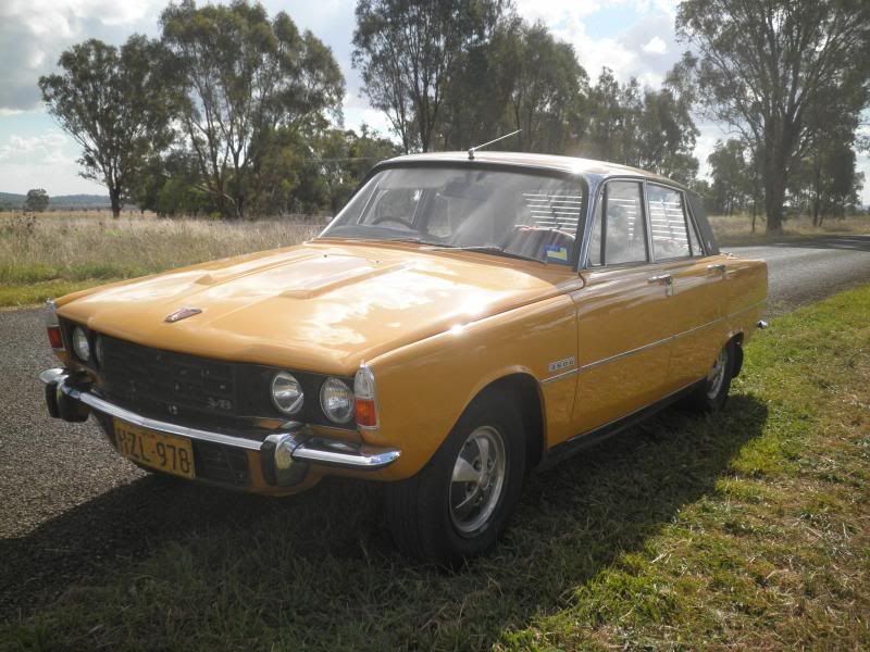
Having fitted my refurbished n/s Saffron doors, it seemed the appropriate time to add some finishing touches.
My Rover had been wearing a mismatched pair of mudflaps for a number of years, the n/s original rubberised canvas item and one of Scott’s (from Scott’s Old Auto Rubber) o/s offerings. So why not replace both!
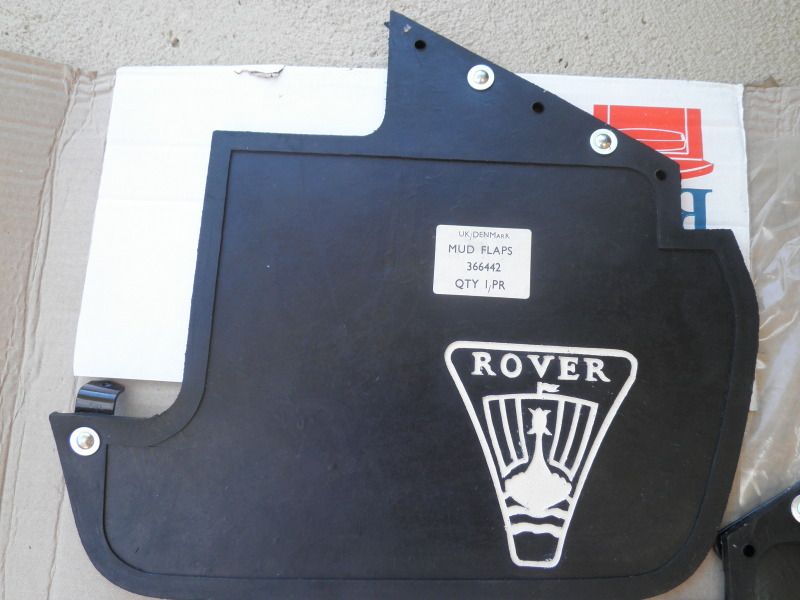
Some years ago I was very lucky in that I was able to purchase a NOS pair of 1964 embossed Rover 2000 mudflaps.
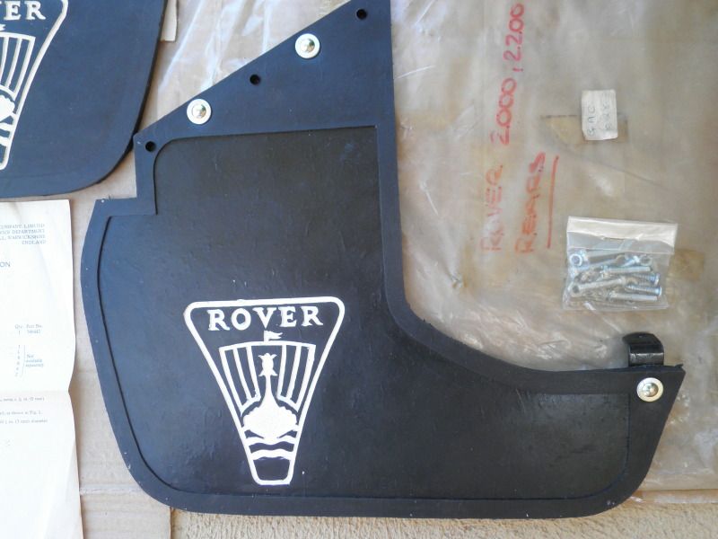
Nearside.
Offside.
So the old flaps were removed and this lovely pair fitted last Sunday. The o/s went on without a hitch, but the n/s needed a little remodelling to clear the exhaust, although I am pleased to say nothing too severe.
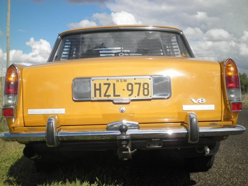
All together.
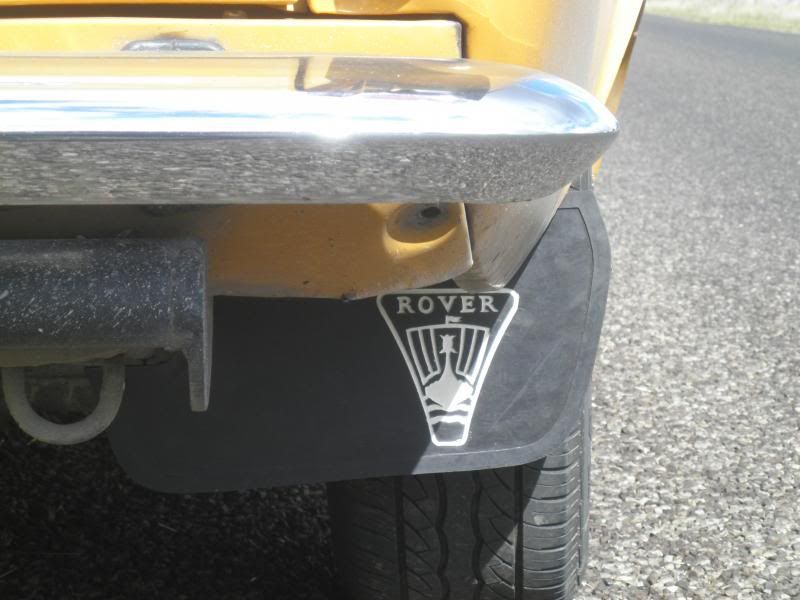
Offside.
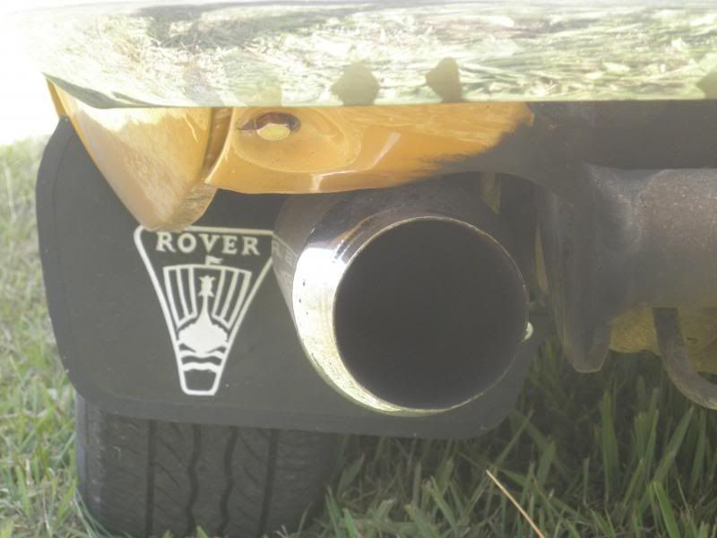
Nearside.
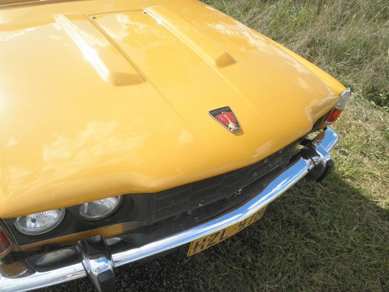
Next it was the turn of the bonnet badge. My Rover had been wearing the same badge since April 15, 1986. I had purchased that badge from my local Rover dealership only weeks earlier, so I could replace the 1974 original, which had cracked very badly. The 1986 replacement faired much better, with the paint dropping out of the sails only in recent years. It too suffered from cracking of the plastic, but after 27 years that was to be expected.
So the time had come for its successor to take up active service, having been slumbering within its original packaging in a dark cupboard for the past 23 years.
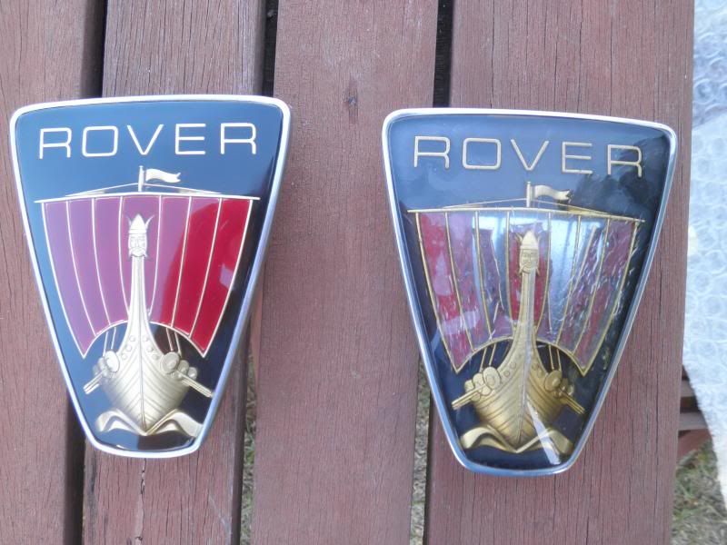
New alongside old.
The old badge was removed and the new one fitted. I noted that the bolts that retained the bonnet lock were of the type used in semi-finished threads. I ran a ¼” X 28TPI UNF tap through the threads so as to clean them up nicely, then refitted the lock retaining it with some new grade 5 bolts. The bolts along with the badge threads were treated to some anti seize lubricant so as to prevent problems down the track.
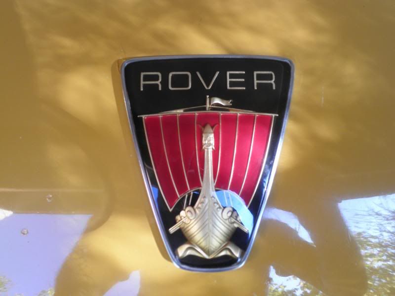
Looking resplendent, the new badge takes its place.
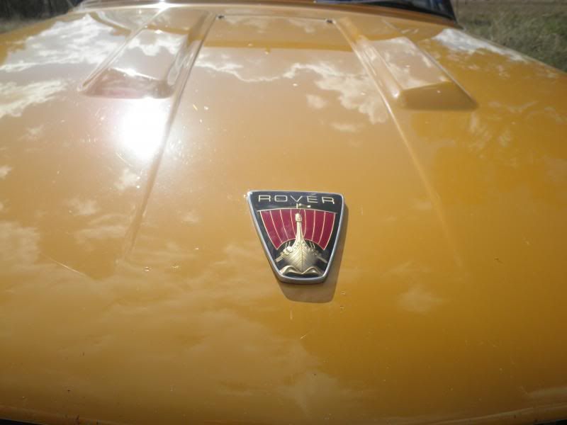
Shining in the afternoon sunshine.
I hope that it serves as well as its predecessor.
Nicely finished.
Ron.
My Rover had been wearing a mismatched pair of mudflaps for a number of years, the n/s original rubberised canvas item and one of Scott’s (from Scott’s Old Auto Rubber) o/s offerings. So why not replace both!
Some years ago I was very lucky in that I was able to purchase a NOS pair of 1964 embossed Rover 2000 mudflaps.

Nearside.

Offside.
So the old flaps were removed and this lovely pair fitted last Sunday. The o/s went on without a hitch, but the n/s needed a little remodelling to clear the exhaust, although I am pleased to say nothing too severe.

All together.

Offside.

Nearside.
Next it was the turn of the bonnet badge. My Rover had been wearing the same badge since April 15, 1986. I had purchased that badge from my local Rover dealership only weeks earlier, so I could replace the 1974 original, which had cracked very badly. The 1986 replacement faired much better, with the paint dropping out of the sails only in recent years. It too suffered from cracking of the plastic, but after 27 years that was to be expected.
So the time had come for its successor to take up active service, having been slumbering within its original packaging in a dark cupboard for the past 23 years.

New alongside old.
The old badge was removed and the new one fitted. I noted that the bolts that retained the bonnet lock were of the type used in semi-finished threads. I ran a ¼” X 28TPI UNF tap through the threads so as to clean them up nicely, then refitted the lock retaining it with some new grade 5 bolts. The bolts along with the badge threads were treated to some anti seize lubricant so as to prevent problems down the track.

Looking resplendent, the new badge takes its place.

Shining in the afternoon sunshine.

I hope that it serves as well as its predecessor.

Nicely finished.
Ron.
Dave3066
Well-Known Member
Keeping busy then Ron
Those rear mudflaps have kept well and they add that little something extra that sets the car off nicely. Will they see much water, or will it be mostly dust? Do you have matching front mudflaps stored away ready for fitting?
The replacement bonnet badge looks great too
Dave
Those rear mudflaps have kept well and they add that little something extra that sets the car off nicely. Will they see much water, or will it be mostly dust? Do you have matching front mudflaps stored away ready for fitting?
The replacement bonnet badge looks great too
Dave
Pretty penny those bonnet badges!!!
Also, I assume that's a factory towbar Ron?
Same as the one I have fitted...my goodness they are a hefty unit.
I had wondered if it was an aftermarket item or a dealer option.
It would be a very sorry modern if it ran into the the back of the Rove with the towbar fitted.
It's actually the main reason I kept mine, even though it probably adds about 35 kg to the car.
vaultsman
Well-Known Member
Looking good Ron. Some great work there that really sets your car off...congratulations!
+1 from me on that. Awful things IMHO.
LeeEFi said:I still don't rate front mudflaps tho...
+1 from me on that. Awful things IMHO.
Dave3066 wrote,...
Hi Dave,
Much appreciate the nice comments Yes, the mudflaps look as if they had only been made yesterday. Only the part number sticker and the original July 1964 instruction sheet give their age away. The gent from whom I purchased them had stored them well for all those years. I don't actually have front mudflaps, in fact I can only recall seeing a couple of P6's locally ever wearing them.
Ron.
Those rear mudflaps have kept well and they add that little something extra that sets the car off nicely. Will they see much water, or will it be mostly dust? Do you have matching front mudflaps stored away ready for fitting?
Hi Dave,
Much appreciate the nice comments
Yes, the mudflaps look as if they had only been made yesterday. Only the part number sticker and the original July 1964 instruction sheet give their age away. The gent from whom I purchased them had stored them well for all those years. I don't actually have front mudflaps, in fact I can only recall seeing a couple of P6's locally ever wearing them. Ron.
billoddie wrote,...
Hi Brenten,
Yes the bonnet badges have always been expensive. I planned ahead so I bought a couple as for many years they were not available. Owners used to fit SD1 badges which were smaller accompanied by a different curve, so they didn't sit properly.
Actually my towbar and no doubt yours too were a dealer fitted item. Like our door mirrors which were also a dealer fitted item, our towbars are all different, depending upon the dealer and the towbar manufacturer. They are an Australian made item, and from what I can see in the parts book, rather more substantial than the Rover factory issue.
Ron.
Pretty penny those bonnet badges!!!
Also, I assume that's a factory towbar Ron?
Same as the one I have fitted...my goodness they are a hefty unit.
I had wondered if it was an aftermarket item or a dealer option.
It would be a very sorry modern if it ran into the the back of the Rove with the towbar fitted.
It's actually the main reason I kept mine, even though it probably adds about 35 kg to the car.
Hi Brenten,
Yes the bonnet badges have always been expensive. I planned ahead so I bought a couple as for many years they were not available. Owners used to fit SD1 badges which were smaller accompanied by a different curve, so they didn't sit properly.
Actually my towbar and no doubt yours too were a dealer fitted item. Like our door mirrors which were also a dealer fitted item, our towbars are all different, depending upon the dealer and the towbar manufacturer. They are an Australian made item, and from what I can see in the parts book, rather more substantial than the Rover factory issue.
Ron.
Vaultsman wrote,...
Thanks very much Stan
LeeEFI wrote,...
Thanks Lee, much appreciated
JVY wrote,...
Thanks Steve Yes I was in two minds for a bit as they looked so good it seemed a shame to use them. Not using them though would ultimately be a bit pointless as nothing will last forever, so best to make use of them and enjoy them. I agree completely, they do offer protection to the lower section of the guards. They will see some wet weather, but the main benefit will be to minimise dirt, stones, loose tar and manure that would otherwise impact the guards directly.
Ron.
Looking good Ron. Some great work there that really sets your car off...congratulations!
Thanks very much Stan
LeeEFI wrote,...
Looking well sorted now Ron 8) I like the rear mudflaps too.
Thanks Lee, much appreciated
JVY wrote,...
I think the mudflaps are a nice touch Ron. In fact they looked so nice and new it was almost a shame to fit them. Mudflaps may not be everyone's cuppa but I reckon they are practical in terms of giving some protection to the rear wings.
Thanks Steve
Yes I was in two minds for a bit as they looked so good it seemed a shame to use them. Not using them though would ultimately be a bit pointless as nothing will last forever, so best to make use of them and enjoy them. I agree completely, they do offer protection to the lower section of the guards. They will see some wet weather, but the main benefit will be to minimise dirt, stones, loose tar and manure that would otherwise impact the guards directly.Ron.
Today just by chance whilst looking over the engine, I noticed that the spill return line had fractured. There was evidence of a slight fuel leak but surprisingly I had not noticed any fuel smell, either under the bonnet or within the car.
I had noted previously that there were stress cracks within the plastic, at the point where the line was moulded over the metal barb. My original line from the filter that linked the two carburettor inlets also had displayed similar stress cracks, and was replaced as was detailed here.
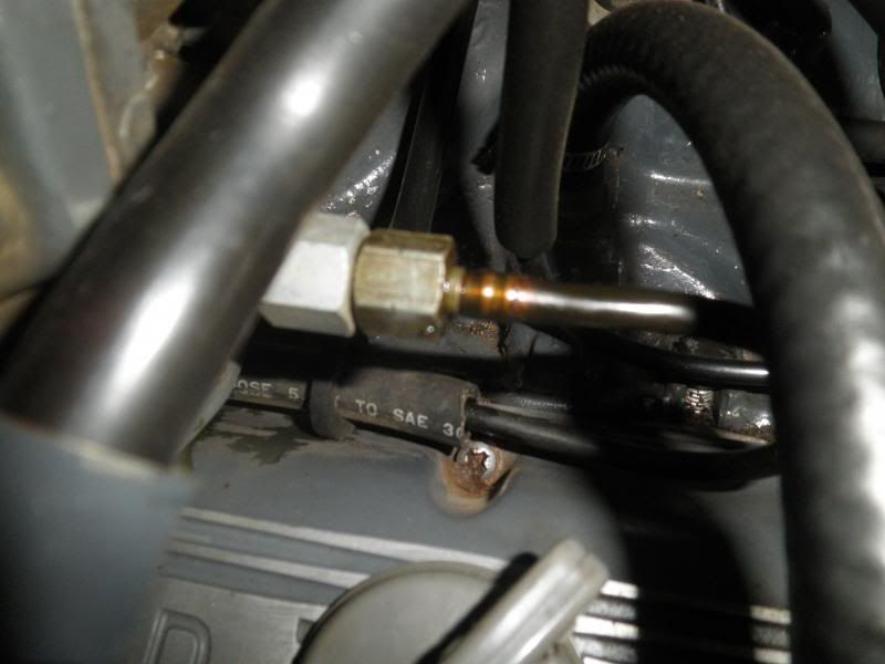
The cracked spill return line. Fuel can be seen on the captured nut. The crack is just before the change in line colour.
Moving the line just slightly resulted in a near complete separation, which had I not noticed would have allowed fuel to pour down over the engine.
The broken spill return line.
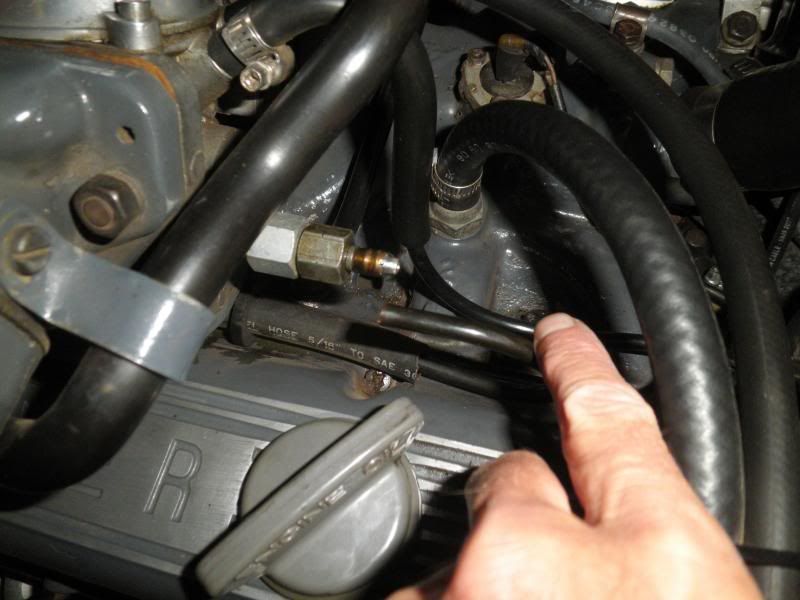
Fortunately, I had a length of ¼” fuel hose in the cupboard, so a short piece was made available to affect a repair.
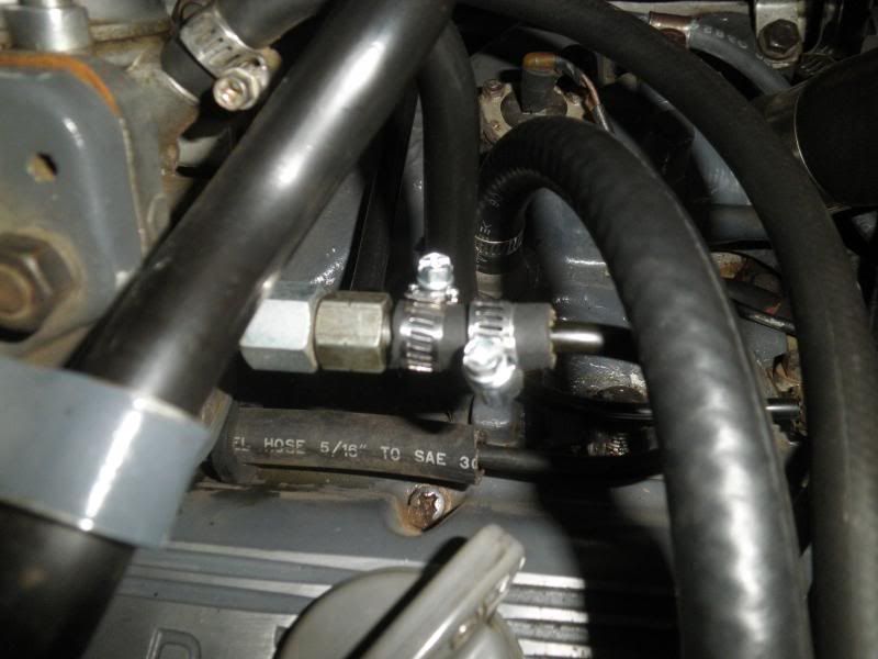
Spill return now repaired.
The rubber hose was a nice snug fit over the plastic line, so the seal that was formed was a good one. At some point the entire line will probably need replacing, but so far that failure point appears to be the only area of concern. I expect it can be put down to both the heat cycles and the movement that the line would experience as the engine moves slightly on the mounts.
It would be a worthwhile endeavour for everyone to inspect their lines and to note any stress cracks that may be evident. The appropriate action can then be taken.
Ron.
I had noted previously that there were stress cracks within the plastic, at the point where the line was moulded over the metal barb. My original line from the filter that linked the two carburettor inlets also had displayed similar stress cracks, and was replaced as was detailed here.

The cracked spill return line. Fuel can be seen on the captured nut. The crack is just before the change in line colour.
Moving the line just slightly resulted in a near complete separation, which had I not noticed would have allowed fuel to pour down over the engine.

The broken spill return line.
Fortunately, I had a length of ¼” fuel hose in the cupboard, so a short piece was made available to affect a repair.

Spill return now repaired.
The rubber hose was a nice snug fit over the plastic line, so the seal that was formed was a good one. At some point the entire line will probably need replacing, but so far that failure point appears to be the only area of concern. I expect it can be put down to both the heat cycles and the movement that the line would experience as the engine moves slightly on the mounts.
It would be a worthwhile endeavour for everyone to inspect their lines and to note any stress cracks that may be evident. The appropriate action can then be taken.
Ron.
SydneyRoverP6B said:It would be a worthwhile endeavour for everyone to inspect their lines and to note any stress cracks that may be evident. The appropriate action can then be taken.
Ron.
Well spotted Ron! The consequences could've been disastrous :shock: Nice neat repair though. I'm guessing over time the plastic fuel lines harden and go slightly brittle. And the vibration of the motor not really helping things.
I recently noticed that my ammeter was moving very slightly about the null position, a behaviour that it does not normally exhibit. It had been some 40,000 Miles (64,000km) since I had last replaced the outer brush, so it seemed opportune to carry out an inspection. With the drive belt removed, the bearings can also be checked for both radial and axial play. Mine had some of the former which when new, you won’t notice any. They felt smooth to turn and had been in there for some 70,000 Miles (113,000km), having fitted them in 2008. It is a good idea to loosen the nut securing the pulley before removing it from the engine, so the belt is temporarily refitted. All the bolts on this 1973 18ACR are metric, so a 22mm socket is used for this task.
With the alternator now removed from the engine, I checked the brushes to start with. When new, brushes are 13.0mm in length with the typical minimum working length being 8.0mm. The inner brush measured 12.5mm whilst the outer was down to 8.5mm, so an ideal time to change it.
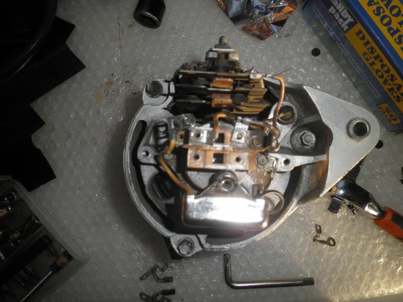
The brushes removed from the brush box can be seen at the bottom of the photo.
Next I decided to replace the bearings as the free play will only worsen which given the miniscule air gap between the rotor and the stator, could lead to contact between the two destroying both in the process.
In order to remove the bearings, the rotor needs to come out, so the pulley and fan are removed initially.
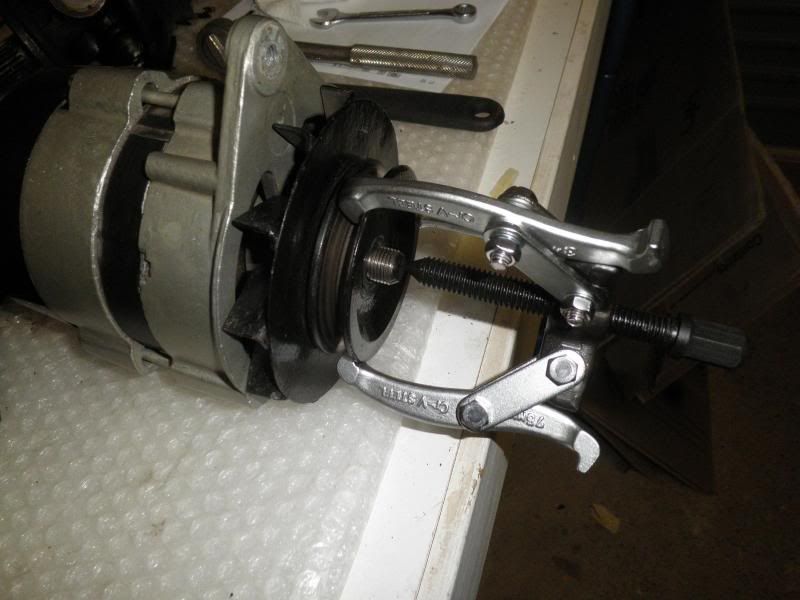
I use a 3” (75mm) puller for this task.
Next the two halves of the alternator need to be separated. There are three long bolts that retain the slip ring end (SLE) bracket to the drive end (DE) bracket . With these out, tap the DE bracket gently downwards so as to release. It is important to remember that the stator is only held within SLE bracket by the phase wires, of which there are three. Keeping hold of both will prevent any unnecessary movement.
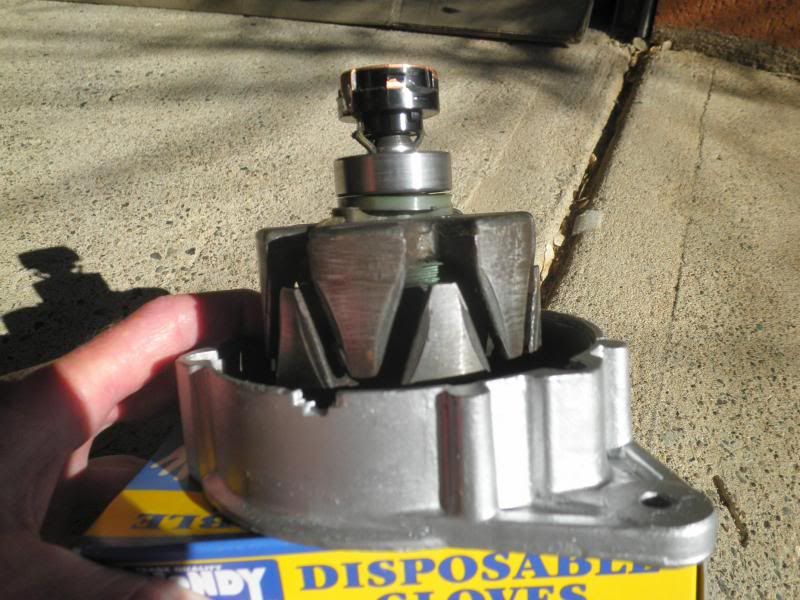
The rotor is retained to the DE bracket by the bearing, while the SLE bearing and slip ring can be seen.
I used the same puller to withdraw the rotor from the DE bearing, which is held within the bracket.
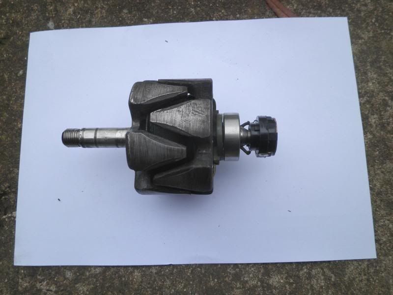
Rotor now free of the DE bracket.
To remove the bearing from the DE bracket, the circlip is released followed by the retainer plate. The bearing can now be tapped out of the bracket, which will be followed by the pressure ring, the striker plate for the oiler and finally the oiler, which is just a felt ring. Fitting the new bearing is just a reversal.
The slip ring was noticeably worn when compared to a new one, in addition when viewed in strong sunlight, cracks could be seen in the plastic, both on the top surface and on the side. I had fitted it at the same time as the bearings back in 2008, so very opportune to replace.
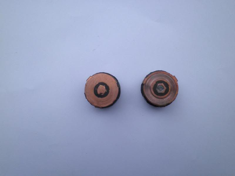
The new slip ring alongside the old one.
Before fitting the new slip ring, the old bearing is removed. As I don’t possess a puller small enough at this stage for the task, I held the rotor gently in a vice and tapped the bearing from behind with a cold chisel, alternating from side to side until it was off. It only took a few minutes and this method also prevents any damage occurring to the rotor shaft, which is not case hardened. The new bearing is fitted by using a tube to rest on the inner shoulder and then with a hammer, tapped down into place. It does not need to make contact with the nylon pressure ring beneath, indeed there should be a small gap left between the two.
The new slip ring is fitted along with a new spring clip and then the wires soldered on.
The solder needs to be a high temperature type possessing high electrical conductivity, so I purchased a length from an auto electrical business that overhaul alternators and starter motors etc on trucks.
The rotor can now be refitted into the DE bracket bearing using a suitable tube such as a socket and the use of a hammer. With the rotor resting within the jaws of a vice and the narrower distance piece in position, the DE bracket is positioned over the rotor shaft and then driven into place.
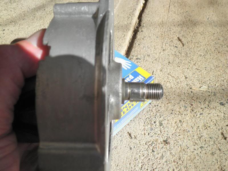
The rotor refitted to the DE bracket. The wider distance is positioned prior to fitting the key.
The two halves of the alternator can now be reacquainted, tightening the three long bolts gently and evenly until all are fully home. The fan fits over and behind the key while the pulley locates on the key where it will capture the fan against the distance piece.
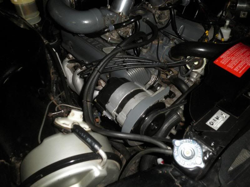
All back together.
The nut securing the pulley can be tightened fully once the belt is refitted.
Ron.
The time had arrived today for a change of spark plus. The set that were being replaced were fitted in July last year, and had delivered just over 23,000 Miles (37,000km) of sterling service.
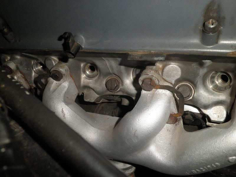
Old plugs out
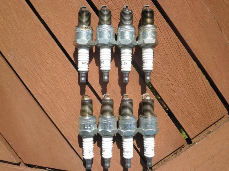
Top row running left to right 7,5,3,1 from the N/S bank. Bottom row, also left to right 8,6,4,2 from the O/S bank.
I also changed the flame traps, fitting a reconditioned pair. Unlike my Rover's original engine, combustion particles (dry dirt and chunks of grit) are not a problem with the 4.6, so flushing the traps with degreaser leaves them just like new, ready to serve again at a later date.
Greasing the tailshaft uni joints plus sliding joint along with a differential oil change completed the major tasks for the day.
Ron.