1967 2000TC - HOT

I removed the switch from behind the dash this afternoon (it is cramped under there) and none of the wires are live - it looks like the centre wire should be permanently live in order for the parking lamp circuit to work, but there's nothing. The switch was ok until I snapped a terminal off, so I've got some more head scratching to do on this I think.
 
Paul

From my wiring diagram, yours should be the same, the live feed comes onto terminal 2, which from memory is I think the top left as you look at the back of the switch. From there it goes to the RH sidelight via terminal 1 (top right) and the LH sidelight via terminal 4 which I think might be the single one in the middle. Making the switch to the sidelight position also makes the link to allow the power through to the headlamp switch. So with the switch disconnected you should only have 12V on the connector going to terminal 2. If you have nothing there then that's your problem. That or a bad earth. There should be a pick up point for the power behind the driver's knee bin. If the parking lights works then there must be power to the switch.

The body of those switches is used in a number of different cars. It's the kinked switch itself which seems unique to the P6. If the switch is broken you should be able to get another similar one and swap the body over.

Dave
 
These switches, in fact all the S1 switches and all variants, including US, LHD etc of the column stalks are still available new from Holden's.

Chris
 
Dave3066 said:
So with the switch disconnected you should only have 12V on the connector going to terminal 2. If you have nothing there then that's your problem. That or a bad earth. There should be a pick up point for the power behind the driver's knee bin. If the parking lights works then there must be power to the switch.

The body of those switches is used in a number of different cars. It's the kinked switch itself which seems unique to the P6. If the switch is broken you should be able to get another similar one and swap the body over.

Dave

There's no power to any of the terminals on the side light switch. My understanding of the wiring diagram is that the side light (and hence headlight) feed is taken from a brown wire which also powers the ignition and main beam flasher, both of which work correctly, so I'll run a temporary 12V feed from somewhere else and see what happens.

I think I can eliminate an earthing problem because the stop lights and indicators all work correctly.
 
testrider said:
There's no power to any of the terminals on the side light switch. My understanding of the wiring diagram is that the side light (and hence headlight) feed is taken from a brown wire which also powers the ignition and main beam flasher, both of which work correctly, so I'll run a temporary 12V feed from somewhere else and see what happens.

Probably just a connector that has come adrift then. My car has the old style wiring and has a brown supply to the switch and a red/black from switch to one of the sidelights and a red to the other. I say red but it is more a dull hint of red and the red/black is mostly dull red with thick black dashes. Wiring diagram below to confirm, or help.... :D

lightswitch66.jpg


30 is the sidelight switch, 31 headlamp switch

Dave
 
Thanks Dave, I have the same wiring diagram here. Basically the brown wire that goes to pin no. 2 on switch 30 has no power. There's a 4 way connector just up stream which I think I've located under the dash but I can't get a multimeter in to it, however the ignition, main beam and horn are all powered by that wire and work correctly. :?

Anyway, I've fitted a new lead from a 4 way connector under the steering column which had a spare hole straight to the sidelight switch and everything works as normal now. I've also repaired the switch too as I broke off terminal no.4, so I soldered a wire and a spade connector in it's place.

I've got one day left on the MOT so I can use it for a run up to the Peak District for work tomorrow.
 
As I've done a bit of car shuffling over the last few days I ended up with both P6's at home for the first time so I thought I'd photograph them together.

DSCN7901.jpg


DSCN7905.jpg


DSCN7903.jpg


I don't have one photo of HOT where it's not covered in rain, but it's back in the garage now as the MOT expired yesterday.

DSCN7904.jpg


Next bit for renovation is the fuel filler area below the rear screen and then the boot floor.......
 
Looking very smart Paul! Nice to see the 2000 back outside after all of the work you've carried out! EMF looks brilliant as ever!
 
It was only outside for a few days but it was good to get a drive in it again. The MOT ran out on Thursday so it was back in my parents garage again for more rust removal. As I said earlier in the thread I had originally planned to just sort the two holes in the floor as advised in the previous MOT and then re underseal it, but I've decided to repair the base unit thoroughly as it's worth doing properly.

With that in mind I removed the rear wings, boot lid and decker panel to get access to the fuel filler area and boot floor.

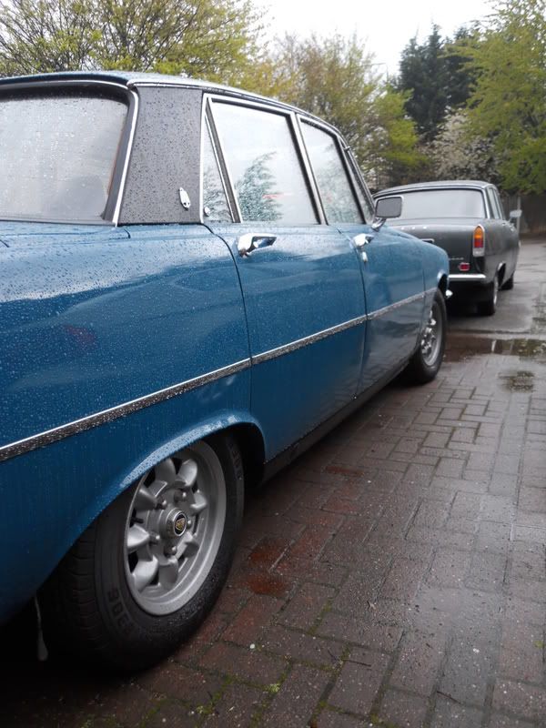
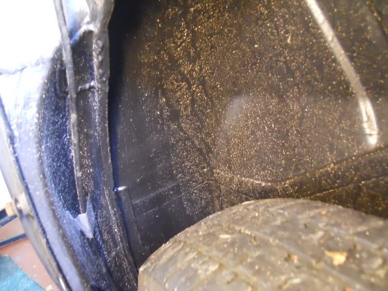
Here's a shot of the freshly painted N/S rear wheel arch after 95miles of Peak District driving. It will all clean off of course, but I'm surprised at how quickly the dirt has built up.

DSCN7912.jpg


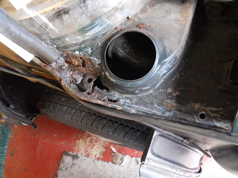
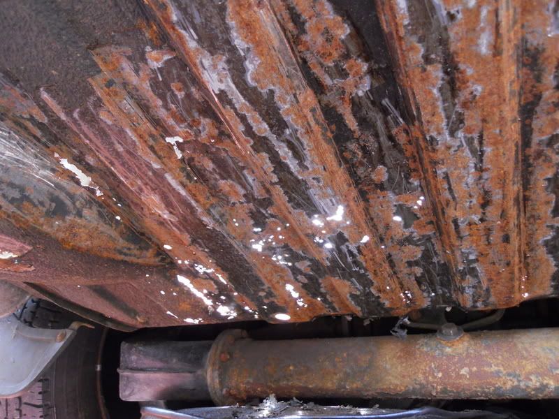
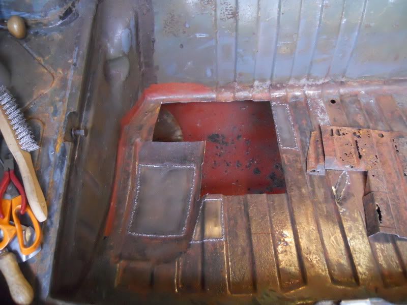
Panels off and a bit of digging and scraping with a chisel left this little lot.

DSCN7913.jpg


It extends up behind the rear screen seal so that will have to come out for the repair. That lot was covered with aluminium mesh and under seal.

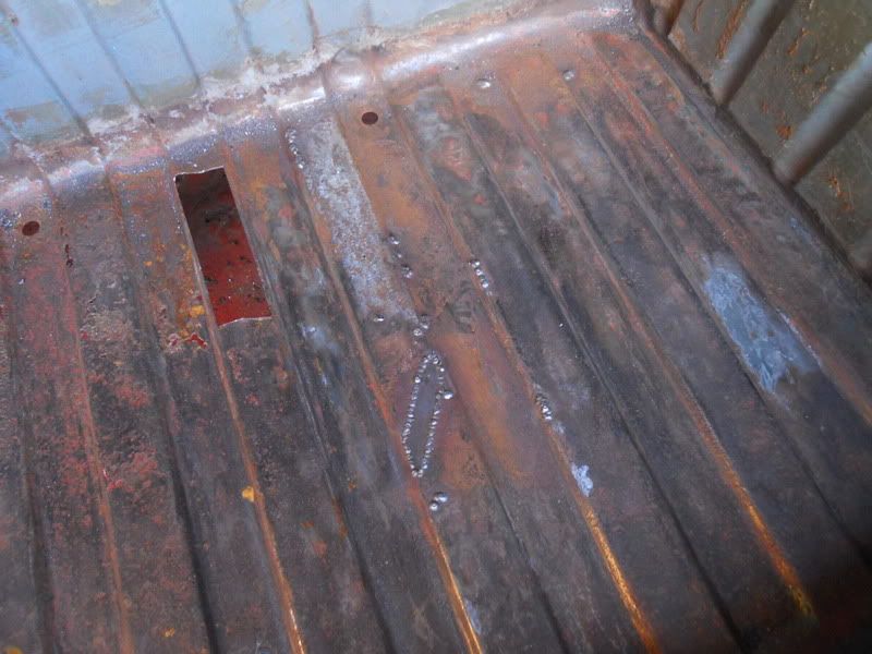
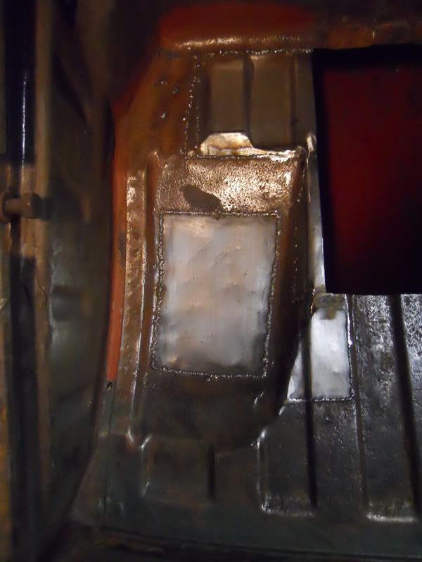
Note the mysterious hole to the right of the picture - I asked about this in another thread, but we never really got to the bottom of why it's there - anyone got anymore ideas? It's almost certainly played a part in this though....

DSCN7915.jpg


When I got the car the boot was full of water and the horse hair mat soaked was through. Water is dripping through from the decker panel are and draining into the boot. There are narrow rusty trails that all lead back up to that area.

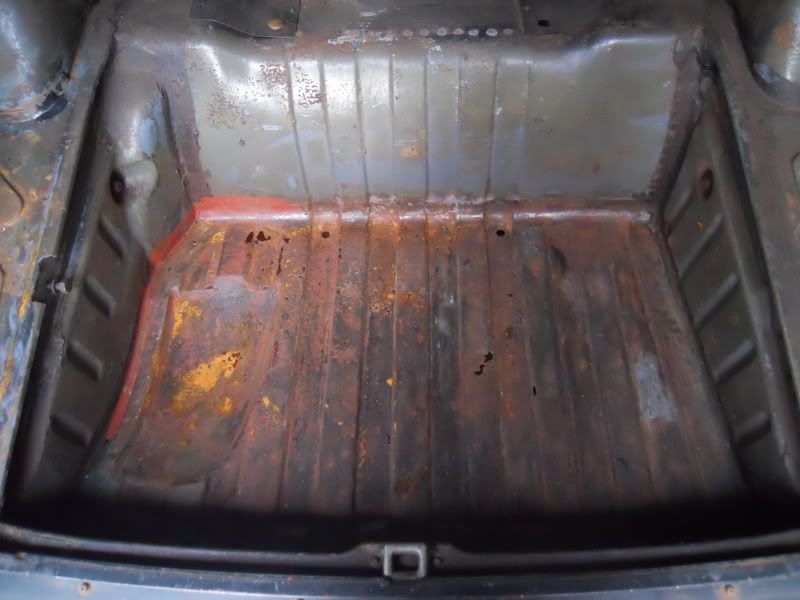
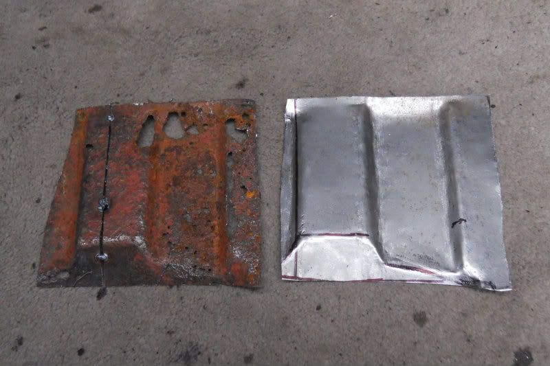
Rover boot floors made by PG Tips!

DSCN7916.jpg


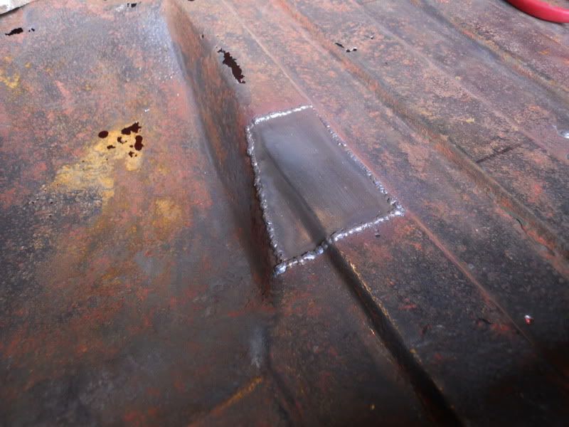
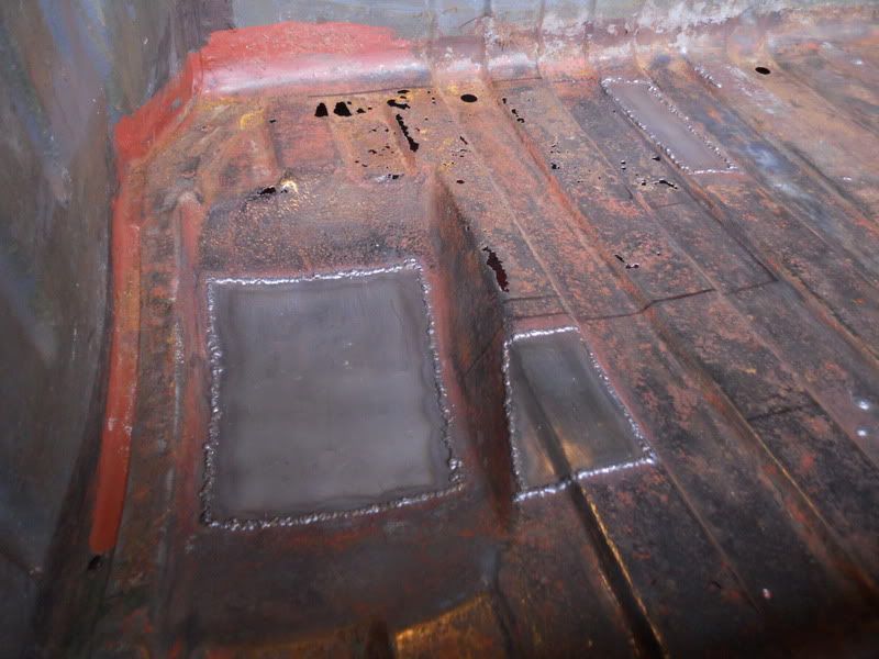
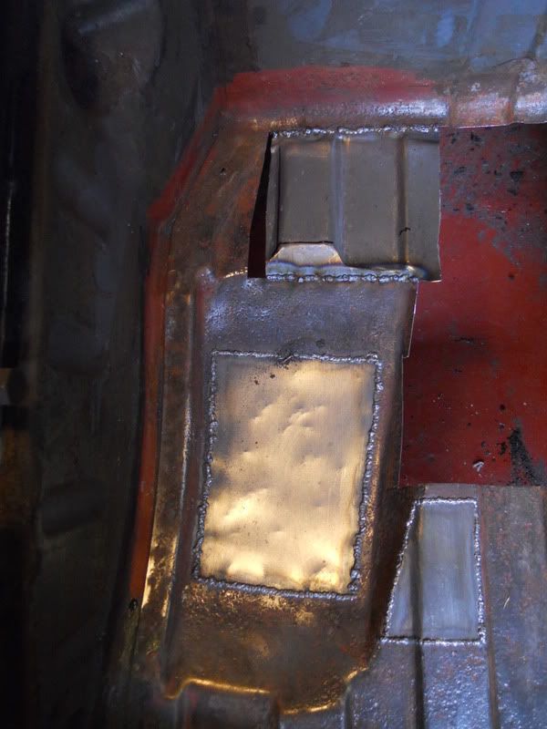
I started on the right hand side repairing the smaller pitted holes which can be blobbed up with weld as the surrounding steel is still thick enough, but the larger areas need cutting out.

DSCN7920.jpg


I wanted to get a bit more done, but F1 qualifying was about to start so I finished for the day.
 
testrider said:
Probably, although the stubbon streak in me wants to have a go at repairing it just to see if I can.

That's the spirit Paul :D

I spent about 3 hours yesterday just shaping a short 5 inch curved repair section for Verity's inner wheel arch. Have you tried shrinking 1.6mm steel the hard way yet?

Dave
 
Dave3066 said:
testrider said:
Probably, although the stubbon streak in me wants to have a go at repairing it just to see if I can.

That's the spirit Paul :D

I spent about 3 hours yesterday just shaping a short 5 inch curved repair section for Verity's inner wheel arch. Have you tried shrinking 1.6mm steel the hard way yet?

Dave

No, I'm only using thin stuff for this. The plates I made for the jacking points were 1.6mm I think and they were pretty tough to shape - just one 20º bend and a chamfer.

I don't view this as a restoration, it's an excercise in problem solving and testing/developing my metalworking skills. The resulting nice car at the end almost seems like a happy byproduct*.

*this view may change when I start duplicating work on the other side!
 
testrider said:
Probably, although the stubbon streak in me wants to have a go at repairing it just to see if I can.

Where there's a will there's a way :mrgreen:

Nice work as always Paul, and you can :wink:
 
With that in mind Jim I set to making a former for the ribs in the boot floor. Nothing fancy, just a couple of bits of wood screwed together to make the right step shape so that I could bash the steel sheet roughly the right profile.

DSCN7941.jpg


That allowed me to make this piece first.

DSCN7942.jpg


I then filled in the spare wheel hollow to add support.

DSCN7943.jpg


Once that was strengthened I got the cutting disc out and made a big hole.

DSCN7944.jpg


As it would be too complex to make in a single panel, I chopped the piece I'd cut out into the sections that I wanted to replicate and made this bit first which was supposed to filled the smaller square at the back.

DSCN7946.jpg


It actually ended up slightly too narrow on the left hand side so I cut a bit more out so that there was room to add a section in after.

DSCN7948.jpg


Here it is with that section filled in plus the side of the spare wheel well added in too.

DSCN7951.jpg


Now I'm just left with the relatively simple rectangle in the middle to do, plus a bit of grinding.
 
Nice work with the boot floor. I did mine a while ago, as you say - made by PG Tips.
I really love the look of your clear front indicator lenses, so much so that i've got a pair winging their way hopefully to me soon.
Keep up the good work.
Glen.
 
Ah, but it's taking 3 times as long! I spent almost 2 hours last night on making the rectangle shape for the last piece of boot floor and it's still not ready to be welded in yet.
 
Back
Top