

You are using an out of date browser. It may not display this or other websites correctly.
You should upgrade or use an alternative browser.
You should upgrade or use an alternative browser.
(Budget) Historic Rally Car Project
- Thread starter Kman1600
- Start date
Gargo
Active Member
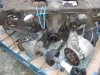
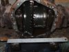
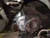
Over the last couple of weeks I've been working at the Jag independent rear suspension (IRS) with a view of replacing the Rover suspension. Much as I love the De Dion, the transmission is weak part of the P6 drive chain. A Jag diff is a USA Dana made Salisbury LSD, used as standard in all IRS Jag inc. XJS, it is a strong strong back end. Although we could use the diff alone and fit it to the Rover De Dion we have gone with the Jag suspension as that is what the works Rover did in the 70's. This keeps our mod a period item.
So far I've got a Jag IRS complete:
Look at the size of the LSD:
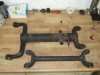
Dismantled it, obtaining the Lower Control Arms (LCA) and half shafts, these will be shortened by 3.125" to bring the hub face to hub face dimension the same as the standard Rovers. This will allow the standard wheels to be used inside an unmodified body.
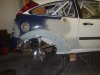
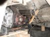
Put the Rover in the garage and removed the rear suspension:
I'm happy to see the fabricated diff mount is still in good condition:
Next to do is dummy mount the Jag diff in the Rover and measure up a propshaft.
So far I've got a Jag IRS complete:
Look at the size of the LSD:
Dismantled it, obtaining the Lower Control Arms (LCA) and half shafts, these will be shortened by 3.125" to bring the hub face to hub face dimension the same as the standard Rovers. This will allow the standard wheels to be used inside an unmodified body.
Put the Rover in the garage and removed the rear suspension:
I'm happy to see the fabricated diff mount is still in good condition:
Next to do is dummy mount the Jag diff in the Rover and measure up a propshaft.
Attachments
I shall be watching this with great interest! I do think you're going to miss the de dion though. The Rover racer (the second one stuck with the de dion) got away with the Jag suspension by having really stiff springs for circuit racing so that rear wheel camber was effectively fixed. You'll need much softer ones for rallying and I'd put money on the Rover's famous traction and planted rear being a very distant memory.
Oops! That came out a tad stronger than I'd intended. The Jag diff is the only tolerably economical way of getting an LSD in a P6 though. And you do get rid of the Rover diff output shafts (which are the only dodgy bit of the Rover diff).
Keep the photo's coming!
Chris
Oops! That came out a tad stronger than I'd intended. The Jag diff is the only tolerably economical way of getting an LSD in a P6 though. And you do get rid of the Rover diff output shafts (which are the only dodgy bit of the Rover diff).
Keep the photo's coming!
Chris
Gargo
Active Member
Yes I will miss the de dion, but hopefully only as a P6 interest. Part of wish list for the change is to keep the body and chassis untouched, yes this will limit the tyre width. I don't do body work and the thought of spending hours slaving away at blending wheel arches is not appealing to me.
If we keep the body standard then we can put the De Dion back in with the Jag diff. So it's as much an interesting project as a hoped improvement.
The thinking is that the front wheels have little if any camber recovery in roll, so we are making the rear similar to the front in that respect. This should help the balance of the car. Once the LSD is in we fit a stiff anti-roll bar to the rear, reducing the roll of the whole car, even with 'soft' springs. That should help the front grip.
As you say Chris the cost is a major part of this project, the whole Jag IRS was £250 with what looks like new disks, pads; yes that's an LSD with better brakes all for £250, that's about 1/10 of fitting a LSD and brakes to the P6 diff.
I'll not take you bet on as this is a budget project and betting unless I'm sure to win will has no place here
Don't worry I too am sold on the traction from a De Dion rear end, but let's compair a Jag IRS to a P6. Just think of this a controlled experiment.
Here's a De Dion I designed from scratch for a rear wheel drive Ford Focus, I only did this to offset my removing the De Dion from the Rover. The owner has remarked on how great the traction is and how predictable the rear is. De Dions Rock...
Attachments
That Escort looks awesome! Yes - I still call them Escorts too!
I really approve of your mods on the basis of experimentation. My dream experiment on the P6 is to replicate the de dion, elbows and trailing arms in 6000 or 7000 aluminium. I've thought carefully about what sections etc would be needed and I reckon it's pretty easily do-able, albeit rather pricey in both materials and skilled welding. Design wise, I reckon the P6 is sufficiently over engineered to justify just going for section for section against the original steel.
Best of luck and keep the pictures coming!
Chris
As Chris says, keep the pictures and write-ups coming, budget engineering solutions are brilliant! By the way, what ratio have you got? Is there enough material on the hubs to re-drill them from 4.75" to 5" pcd as some hubs, like the Rover ones aren't really suitable for re-drilling?
Are you going to add any adgustment into the Jaguar lower arms, they are shimmed from the factory on the brackets that locate on the diff housing to get the alignment just right. As you are sort of delving into the unknown it would possibly be a good idea to build in ways of fine tuning and tweaking the alignment depending on how well it works, or even for different road surfaces if it makes that much of a difference?
As for propshafts, I've got a modified Rover P5 two piece propshaft in mine, and for another project I've aquired a Rover P4 two piece propshaft to modify which is near enough identical but I'm sure the fixed lengths are different, I could measure them if you're interested? I've tried to keep as much as possible Rover derived or British Leyland parts bin on mine for the sake of it
Another idea which I have seen is to copy the period Aston Martin de dion rear end. It uses a similar Salisbury 4ha casing and presumably identical internals from what I remember but has a fixed de dion tube. The driveshafts are telescopic on roller bearings to prevent any form of lock up, although getting hold of any of these parts I guess would be horrifically expensive!
[quoteThe driveshafts are telescopic on roller bearings to prevent any form of lock up, although getting hold of any of these parts I guess would be horrifically expensive][/quote]
Some old Datsuns/Nissans had telescopic driveshafts with roller bearings , back in the 70's if it's any use .And aren't some similar ones used as a conversion on Triumph TR's/Stags to prevent spline lock-up?
Some old Datsuns/Nissans had telescopic driveshafts with roller bearings , back in the 70's if it's any use .And aren't some similar ones used as a conversion on Triumph TR's/Stags to prevent spline lock-up?
Gargo
Active Member
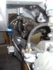
This weekend I've got the mocking up of the installation done. I've some questions at the end of the post for you people who know the rover shell a little better than I.
I started by measuring the angle of the V8 and found it to be pointing up by 5 degrees at the front. I need this to keep both ends of the propshaft parallel to stop vibration due the propshaft having UJs rather than CVs.
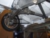
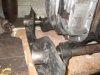
So I put the diff under the car and raised the nose by 5 degrees. Then had to lower it to 2.5 degree to get the lower control arm mounts to point at the cross beam which runs under the propshaft.
I need this as I want to mount radius arms to the cross beam from the Jags hubs. This is very much like the Rovers setup.
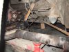
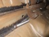
I was able to check clearance for a single propshaft running from the gearbox to the diff. Here the wood is holding the shaft higher than is needed so the clearance will be better than is shown.
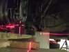
Here the diff is fitting quite well under the car. I was able to the outputs the same position as the P6's.
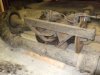
I'm going to mount the rear of the diff in a similar way to the mount I made for the P6 diff. Just a frame that mounts onto the standard mounting holes in the boxed cross member. The diff will be solidly mounted with no rubber. We ran the P6's diff this was and the noise level was fine, the whole rear suspension will be mounted solid to the car and if there is a noise issue then so be it, it can't be never be as bad as mini so that's ok.
The front mount is a little trickier as there is nothing in the P6 chassis to mount to. I could go to the spring/damper mounts but that's not that easy, so I'm thinking of mounting to the boxed section that runs between the spring mounts across the car. Here's a photo of some wood going between the front LCA mount and the boxed section on the car.
I started by measuring the angle of the V8 and found it to be pointing up by 5 degrees at the front. I need this to keep both ends of the propshaft parallel to stop vibration due the propshaft having UJs rather than CVs.
So I put the diff under the car and raised the nose by 5 degrees. Then had to lower it to 2.5 degree to get the lower control arm mounts to point at the cross beam which runs under the propshaft.
I need this as I want to mount radius arms to the cross beam from the Jags hubs. This is very much like the Rovers setup.
I was able to check clearance for a single propshaft running from the gearbox to the diff. Here the wood is holding the shaft higher than is needed so the clearance will be better than is shown.
Here the diff is fitting quite well under the car. I was able to the outputs the same position as the P6's.
I'm going to mount the rear of the diff in a similar way to the mount I made for the P6 diff. Just a frame that mounts onto the standard mounting holes in the boxed cross member. The diff will be solidly mounted with no rubber. We ran the P6's diff this was and the noise level was fine, the whole rear suspension will be mounted solid to the car and if there is a noise issue then so be it, it can't be never be as bad as mini so that's ok.
The front mount is a little trickier as there is nothing in the P6 chassis to mount to. I could go to the spring/damper mounts but that's not that easy, so I'm thinking of mounting to the boxed section that runs between the spring mounts across the car. Here's a photo of some wood going between the front LCA mount and the boxed section on the car.
Attachments
Gargo
Active Member
Only 5 attachments they say????
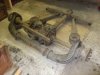
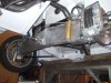
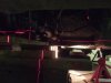
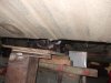
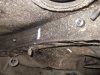
And the whole thing mocked up looks like this.
The photo shows the LCA (lower control arm), which mounts under the diff. At it's outer end is the hub, but also the radius arm which here is the rusty rod going forward to mount to the cross beam just inboard of the P6's radius arms mounting points. The position of the radius arms mounting points has to be in line with the two LCA mounts under the diff. If they are not bang on the suspension will either bind when trying to move or bend either the suspension or the car chassis.
Other things missing in the photo is the drive half shaft. It is a fixed length like the Rovers but unlike the Rovers it controls the camber of the rear wheels. The camber is adjusted using spacers in the half shafts. The inboard brakes are not there either.
Ground clearance is not to bad either.
You may notice the diff is not held very stiffly in the fore-aft direction, as the radius arms take all the fore-aft loads, leaving only a torque exerted by the LCA on the diff. The drive shaft to the wheel can only pass a torque back to the diff, so the diff will never see a fore-aft force. The subframe behind the diff together with a couple of mounts in front of the diff will take all the torque transmitted and reacted by the suspension.
My questions:
Do you think the box section between the springs is strong? I was planning on drilling through both the rear and forward walls of the box. Welding in a tube that is welded to both the rear and forward faces, together with a strengthen plate on the rear face. The diff mounts will then bolt to this tube.
Attachments
That looks a completely satisfactory plan to me Gav. Things that spring to mind; Is there enough space around those radius arms and the vertical ties off the front of the diff to get the exhaust system through? I'm sure the spring seat cross member is up to the job, but remember that the Jag diff is going to put in larger forces in twist around the half shafts than the Rover diff, because it doesn't have that nice long extension housing to give increased moment on the front pickup. Is the radius arm exactly the same length as the jag one where it meets the suspended Xmember? If not, a bit of thought may be required as to the change in the Jag geometry. At the end of the day, the diff is pushing the car forward. There must therefore be an equal and opposite reaction. It is either going to be taken through the diff mounts or through the radius arms, or both. For that reason, I'd be more comfortable if there was some degree of for and aft bracing to the diff. Perhaps backwards from the rear of the LCA bracket to the boot floor area?
Chris
Chris
Gargo
Active Member
Hi Chris,
The exhaust should fit ok. The radius arm are in the same space as the P6 radius arms, so the exhaust can go over them. The exhaust should pass outboard of the front mounts, where the springs are on a P6. We will be using coil over dampers mounted to the inside of the chassis rails.
The forces from the couple reacting the drive torque will be greater, than a P6 diff, but as long as that spring to spring box is not made of the lightest of material it should be ok. I'm going to pay attention to how the rear mounts are attached to the car. I think a little detail will make things stronger and stiffer than the standard rubber mounts.
Jag installed the IRS in a very different way. The IRS (diff, suspension, dampers, brakes) was complete inside a large pressed steel cradle. This cradle was mounted to the car by rubber mounts at either side of the car, on the top of the cradle only. This would allow the cradle to rock or swing backwards and forwards under the car. To stop the swing the radius arms run from the hubs forwards to the sills, parallel to each other. To allow the hubs to move in arcs on the end of these arms (slightly moving forwards), the rubber mounts allowed the IRS to rotate (when viewed from above). This rotation is a form of rear wheel steering. So yes it is and no it's not the same geometry as a Jag. In both systems the wheel hub moves in an arc around the LCA mounts under the diff, but in the Jag the diff is allowed to twist under the car.
In my setup, the diff is solidly mounted and the radius arms are mounted in line with the LCA lower mounts so no twist will take place and no rear wheel steering.
The diff does NOT push the car forwards in either a de dion or in this IRS setup. The drive/brake forces are passed to the radius arms, so the cross member will take all the drive/brake forces. On the Rover DeDion these forces are taken by the watts linkage arrangement at both hubs, the radius arms and the link from the top of the hub to the pin on the side of the boot. Since this top link is not on the Jag the hub will try to rotate around the join of the radius arm and the hub. The LCA takes this torque back to the diff.
The LCA is only ever in twist and/or compression/tension. No sheer force (drive force) is transmitted down the LCA. As the drive shaft can only transmit a torque the diff will only ever see torque and no fore-aft loads. All this is true until something deflects and then the load paths will go to what ever is stiffest; hence the need to make the radius arm mounts stiff and the diff fore-aft mounts not so stiff.
If I was to support the diff fore-aft I'd take it forwards, probably to the radius mounts again.
Sowen you asked about fitting the Rover Wheel onto the Jag hub. I have checked and there is plenty of material to drill the larger PCD.
I'm going for the single propshaft as it's fairly cheap to buy and with less bearings, has less things to go wrong than two shafts, thanks for the offer. For the adjustment of the geometry, I'm happy with shims. Shims are very stiff, maybe a little fiddly to setup but they are there to be adjusted.
gav.
Guy Engelsman
New Member
I am also contemplating putting a Jag LSD in my car "Pooh".
I have replaced and modified everything else so the diff is the last thing needing doing (350ish horsepower is likely to be a bit much for the standard diff :wink: ). I intend to keep the De Dion setup however, but the way you are planning to mount the diff itself is pretty close to what I planned. Having had a tap about under the car today I would say that using the box section would be OK but I would possibly put a doubler over the area around the new bolt tubes just to be sure. I was planning to use either red polybush or aluminium mounts for vibration reduction, but would be interested to see how a solid mount goes.
I wait with great anticipation for you to finish this project as it will give me the best starting point when I do the same thing later in the year
I am also VERY envious of your laser setup..........
Cheers
GUY
ewokracing
Active Member
I like this idea immensely.
Gargo
Active Member
Not to much to show for today’s work. First lot's of prep and thinking done. I now have a proper CL to work from. As the diff is mounted solid to the car no adjustment is provided for fixing bad alignment after the mounting frames are welded, so the CL is important.
Anyway got to drill holes today. My original plan to not modify the shell has been dropped in the interest of a better mount. Although we'll be modify the shell the standard could still be accommodated.
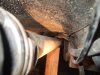
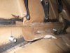
Made a set of attachments to the lower suspension mounts. These tubes are what the frame will mount to and are welded to what remains of the Jag IRS cage.
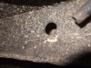
Here are the holes and the mount inserts for the cross member between the std spring mounts. I agree Guy, on drilling i realised the box is made of light gauge so I think a doubler will be a good idea.
And the hard points in place.
I've never felt totally confident on my welding, so when Tim told me my welder is a 'good wee thing', my blaming the tools excuse evaporated. So Tim is planning to weld it all up next Sunday. I'll hopefully have everything drilled, cut, machined, tacked, by then.
The laser is a great job, used it while drilling the holes through the box. To keep the drill bit horizontal, I pointed the laser at the hole and kept the laser line on the centre line of the drill.
Anyway got to drill holes today. My original plan to not modify the shell has been dropped in the interest of a better mount. Although we'll be modify the shell the standard could still be accommodated.
Made a set of attachments to the lower suspension mounts. These tubes are what the frame will mount to and are welded to what remains of the Jag IRS cage.
Here are the holes and the mount inserts for the cross member between the std spring mounts. I agree Guy, on drilling i realised the box is made of light gauge so I think a doubler will be a good idea.
And the hard points in place.
I've never felt totally confident on my welding, so when Tim told me my welder is a 'good wee thing', my blaming the tools excuse evaporated. So Tim is planning to weld it all up next Sunday. I'll hopefully have everything drilled, cut, machined, tacked, by then.
The laser is a great job, used it while drilling the holes through the box. To keep the drill bit horizontal, I pointed the laser at the hole and kept the laser line on the centre line of the drill.
Attachments
unstable load
Well-Known Member
Would an tubular frame for the prop shaft into the diff not take up the forces generated if it's tied to the diff carrier frame and to the chassis at the same point as the Rover diff is attached?
Kman1600
Member
Gargo said:I've never felt totally confident on my welding, so when Tim told me my welder is a 'good wee thing', my blaming the tools excuse evaporated. So Tim is planning to weld it all up next Sunday. I'll hopefully have everything drilled, cut, machined, tacked, by then.
The laser is a great job, used it while drilling the holes through the box. To keep the drill bit horizontal, I pointed the laser at the hole and kept the laser line on the centre line of the drill.
Hi Gav.,
I think you underplay your own welding capability, after all we’ve tested your diff support bracket pretty extensively with no sign of failure and I’ve seen the complex exhausts you’ve made in the past for your Hillclimb car 8) Also you might be overplaying mine, feeling the pressure now :roll: but we’ll give it a go on Sunday!!
As always your design and fabrication skills amaze me :shock:
Tim