Brake Warning Lamp Circuit

testrider

Active Member
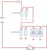
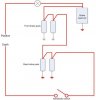
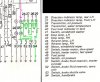
As part of the MOT preparations on EMF I've been trying to get the brake warning circuit to work in order that the lamp shows when the handbrake is applied - something that it's never done. According to the wiring diagram for September 1970 onwards cars the handbrake switch is last in the line on the circuit and connects the circuit to earth when the handbrake is applied.

The low fluid level switch does illuminate the lamp on the dash but, nothing else works. Am I right in thinking the brake pad wear wires and the handbrake switch are all in series and therefore must all be connected in order to work?

If so, I don't have wires on the front brake pads, but I have connect the black/white wires together on each side of the engine bay in a hope to complete the circuit and power the handbrake switch. However, even though there appears to be continuity from side to side I can't get 12v from any of the bullet connectors. Any ideas where the 12v feed for the warning lamp originates from?

Or, should I forget about it and just take it for the MOT without the handbrake on lamp?
 
testrider said:
Am I right in thinking the brake pad wear wires and the handbrake switch are all in series and therefore must all be connected in order to work?

Correct. The handbrake switch is the test for the entire pad waring light system. The reservoir low warning switch works independently of that, the only connection being the live side of the reservoir switch is where the supply for the pad warning light system is picked up. If you have the pad warning light plugs on their little loom on the car, but no wires on the pads, you need to bridge all the plugs on the loom to cheat the system and get the light to work
 
That's how I understood it worked too.

My car has pads with no wires and my handbrake has never brought the light on. Switch works ok, but no supply to it because the pads have no wires to complete the circuit. I wouldn't worry about it for the MOT.

Dave
 
Thanks fellas. I thought handbrake lights were in the MOT now?

My rear pads have wires, but the fronts don't so I've connected the wires together where the bullet connectors are in the engine bay but none of it is live even with the handbrake on. Reckon I'll forget about it an book the MOT then.
 
webmaster said:
You can be the test case, we'll find out if it's a fail or not :D

If the tester says anything just tell him that it's a low fluid warning lamp, and if he questions it you can show him that it works then. I think the wording in the testers manual will be that the lamp has to work, but it won't go into specifics about the exact method of operation, and in this case, it works.
 
Handbrake warning lamp isn't much use anyway, worked perfectly on my wifes old 820, but she still managed to drive around with the handbrake on long enough for the rear pads to dissintegrate :LOL:
 
harveyp6 said:
webmaster said:
You can be the test case, we'll find out if it's a fail or not :D

If the tester says anything just tell him that it's a low fluid warning lamp, and if he questions it you can show him that it works then. I think the wording in the testers manual will be that the lamp has to work, but it won't go into specifics about the exact method of operation, and in this case, it works.

Good point Harvey.

Rick, we'll find out next Tuesday lunchtime as it's booked in for 9:15am.
 
On modern cars, its described as tell-tale and if the tester sticks by the letter of the law, it has to work to pass. Its the same case for the tell tale for fog lamps. He would be a pretty picky guy to fail it on that though. Even so, I reckon your best bet is to tell him its a low fluid level lamp.
 
keynsham1 said:
I drew it for another post.

You did indeed, but I think you'll find that it's not correct, because the low fluid level switches should work independently of the pad warning light system, and the way you've drawn it they don't. Any single break in the circuit rendes the whole system useless. The two reservoir switches need to be in parallel with the pad warning light system, and each other.
 
harveyp6 said:
keynsham1 said:
I drew it for another post.

You did indeed, but I think you'll find that it's not correct, because the low fluid level switches should work independently of the pad warning light system, and the way you've drawn it they don't. Any single break in the circuit rendes the whole system useless. The two reservoir switches need to be in parallel with the pad warning light system, and each other.

But they are in parallel on the diagram, aren't they?
 
darth sidious said:
But they are in parallel on the diagram, aren't they?

They are after the pad warning light system, but the handbrake switch should be between the last pad and earth, and the two reservoirs should have the ignition supply directly to each of them, through the switches to earth, and the pad warning light system should take its supply from the live side of one of the reservoirs. So on that illustration after the last pad the circuit should go to the handbrake switch and then to earth, not through the reservoirs. At the top of the pic there should be a split in the supply before the pads, which goes to the two reservoirs as a parallel circuit to the pads. In other words break the link between the last pad and the reservoirs, and take the supply for the reservoirs from a point before the first pad. Operating the handbrake only tests the pad warning light system, that's why checking the reservoir switches is a service item. The way it's been illustrated the handbrake switch is testing the reservoirs as well. It would be so much easier if I could draw it out ......
 
I understand you Harvey :) .
testrider, If you have a multimeter you could do some quick tests that might identify the problem:-

1. At the handbrake switch, with brake off (i.e. switch open), use a mulimeter to test for +12V on the contact of the switch that is connected to the +12V live pickup on the resevoir. If you don't have meter, you can use a small 12V bulb. If there is no 12V at the handbrake switch contact with the switch open, this means you must still have a break in the wiring between the resevoir and handbrake switch.

2. The other contact on the hadbrake switch should be connected to chassis. You can use a multimeter on ohms setting to check for continuity.

3, If the above tests are OK, check the continuity of the handbrake switch when closed to make sure the switch is working.

You said there was no live (at front pad bullet connectors?) with handbrake on. You wouldn't expect to see live 12V here with the handbrake switch closed if all was working OK. However, I would epect 12V with the handbrake off (switch open).

BTW, good luck with MOT. Unless the tester is familiar with P6's my guess is he won't know about the warning light? He (or she?) will be too busy trying to work out how to turn the ignition on and open the bonnet. :D
 
Sorry to nick your diagram, but I have changed it a bit

This may not be exactly right, but it is almost


The only brake pad switch (bullet connector) to be live with all of the pads disconnected would be the first one that the the circuit goes to, and I'm not quite sure which one it is.

Richard
 

Attachments

  • Brake%20system.jpg
    Brake%20system.jpg
    19 KB · Views: 366
quattro said:
This may not be exactly right, but it is almost

For a single line system that's exactly how it is. For dual line you add another reservoir in parallel to the first one, and fit a PDWS between the last pad and the handbrake switch.
 
My wiring is as per the NADA wiring diagram in the manual as below:


Pink is power in and green is the continuous line through all the components, ultimately reaching earth.
Does this shed any light?
 

Attachments

  • Wiring 01.jpg
    Wiring 01.jpg
    72.6 KB · Views: 339
After I posted correcting your diagram I thought maybe I'd better just have a little check up, and I found a schematic in the book (in the braking section, not electrics) for the dual circuit, and it shows the system wired up exactly how I (very badly) explained it.
 
Back
Top