Air-con Wiring Diagram... and now, Electric Windows.

Fraserp6

Member
Pretty simple one here, does anyone have a V8 delanair wiring diagram. I'm looking to wire in a a V8 air con unit into my 4 cyl 2000tc. I understand a fair bir of fabrication is required, which I'm willing to do, though I need to know what I can and cannot change.

Thanks is advance.
 
Re: Air-con Wiring Diagram

Eeek! Do you mean Delanair - which is the early 4 cyl system - or the factory P6B NADA type system? If the latter I think I can scan and send, I've never seen any technical data for the Delanair though. KiwiRover has a picture of a Delanair on one of his threads - I've yet to see one in the flesh!

Chris
 
Re: Air-con Wiring Diagram

There is a wiring diagram for the V8 system in the Haynes V8 manual. Until you actually have an AC system to use, it's hard to say what bits you'll need. As the V8 setup is slightly more common, your best bet will probably be to use a complete V8 system and just make up a bracket to mount the compressor. I haven't actually put my two setups side by side yet to compare but:
Image0572.jpg

Enginebay.jpg

The compressors and most ot the electrics both live in roughly the same place, the condenser from the V8 may fit the series 2 body and the receiver/dryers are on opposite sides. Behind that, the two systems are completely different so if you're using the V8 system, you won't need any Delanair parts.
Also, if you are buying a second hand system out of a wreck, chances are the condensor, receiver and hoses will be stuffed anyway and will have to be replaced with new so it would be worth talking to an AC specialist about building a bespoke system with whatever parts you have.
 
Re: Air-con Wiring Diagram

The system is out a V8 NADA, apologies for any confusion there.

I imagine after 40ish years that things are a little tired. I would like to get the thing wired up to see if there is any life in the systeml, I guess thats as good a place to start as any.
 
Re: Air-con Wiring Diagram

Fair enough, here's the diagram. However, there is very little electrical stuff involved. You can test the fan switch with an ohm meter, test the blower motor and the compressor clutch with a battery and that's about it! All the temperature and heater flaps are controlled by vacuum (also shown in the diagram) and obviously, you'll not be able to check for leaks or cooling function 'til the system is installed and gassed. Best you can do is make sure the compressor turns over, then fabricate a bracket and pulleys to mount it to the engine (and modify your air cleaner to suit), install the heater box and centre console and hook up all the vacuum controls and then take the car and all the remaining bits to an AC tech and have them fit some appropriate engine bay parts. Enjoy! :D
scan0001.jpg

scan0002-1.jpg
 
Right, putting in the wiring loom for the Rover electric windows from a NADA car. I've pretty much got the idea with the wiring as it filters off to the doors, the wiring on the centre console has two brown an white spade connectors and a green wiring on a spade connector.

I imagine the brown and white is the ignition as its thicker. I then have a second Brown and White wire which is slightly thinner and the Green wire

Is there a voltage regulator or something to wire it into at some point, perhaps behind the centre console?

I might add the 2000 has not had electric windows in it at any point and if there is any additions to the wiring loom prior to fit these initially, they won't present in my car.

I'm sure this is pretty simple, however, I'd just like to check before I start.

PS, Thanks for the diagramme on the air con Kiwirover, I'll be wiring all this up tomorrow. Is it important which vacuum hoses go where?
 
No worries Fraser, I would say that placement of vacuum hoses is as important as wiring and should be treated the same.

Right, windows! Do you have the relay and isolator switch? The green wire is the main power supply to the switches. It runs from a connector near the main lift switches to the relay which should be fitted inside the centre console. Main power to the relay is the brown and white wire. This should run through a thermal cutout switch to a power connection on the back of the ammeter. The switch trigger power lead should be purple and brown and runs from the relay back to the fusebox (ign on connection), and the fourth wire off the relay goes straight to the window isolator switch on the dashboard by the hrw switch.

You really need to find yourself a workshop manual for all this stuff because it is all in the Haynes book.
 
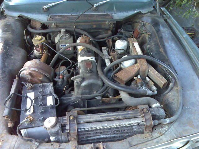
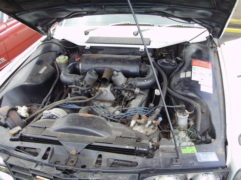
Had a suck on the vaccum pipes, for the most part they seem to work, some move flaps and others move things as I can hear clicking inside the box, so thats all looking good. Had a look at the electric windows this evening, in the wind and the rain, so I decided to call it a night pretty quickly.

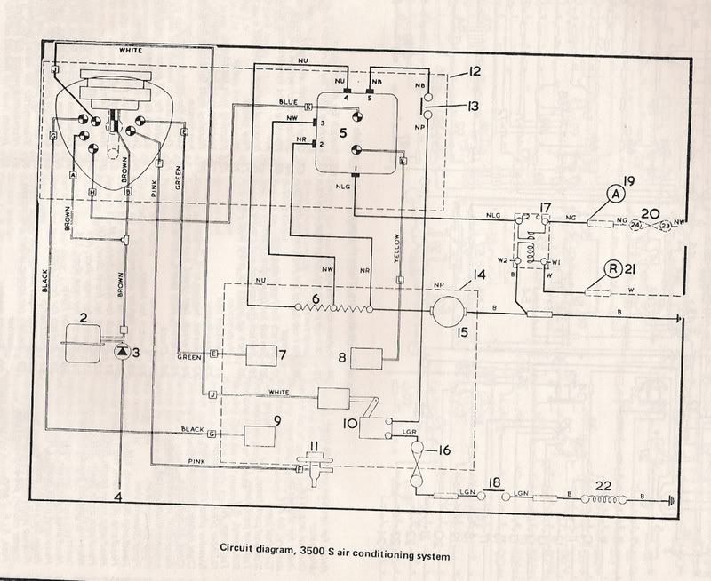
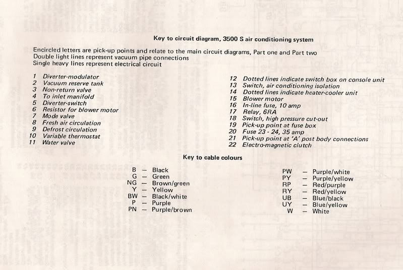
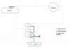
Right, I have a regulator, with thermal cut out attached (made by Otter Buxton England yes?) I can wire from the fusebox to the regulator myself, the same as I can wire from the ampmeter to the back to the regulator myself, however, I don't have a isolator switch, am I able to just do without, taking a wire somewhere else?

Also, the regulator has C1 C2 W1 W2 stamped into it, I assume one brown and white goes to one of those connectors, as does one green, the other brown goes to the thermal cut out which the other connector for goes away to the ampmeter, also my ignition wire from the fusebox. Then I have the isolator taking the final spade connector leading off to the dash near the HRW lead.

does it go a bit like

C1 - From fusebox (Ignition)
C2 - Brown/White to Thermal cut
W1 - Green Power to Switches
W2 - Isolator motor.

cutout pin 1 - brown white
cutout pin 2 - wire from ampmeter

although it says from ampmeter, can I not take a live from anywhere on the car? why specifically use the ampmeter?
 
So was out today at the car, working on the centre console, I've made progress, however, I'm trying to figure out what order the wiring goes into the relay, which I think is where I'm going wrong. I'm don't have an isolator switch, so rather than putting it through an isolator, I was planning to earth the circuit on the chassis.

I've included a scabby amatuer homemade wiring diagram done on paint. I've made some of the wiring up myself, which I've left in grey as its a different colour to the official wiring diagram, though I think serving the same purpose.

Any ideas, where I've made a mistake? if not, I'm assuming I'm not grounding things properly, as they still no life to the motors. There is a short spark as I dissconect the earth from w2 (found this out bt accident.)
 

Attachments

  • Untitled.jpg
    Untitled.jpg
    26.4 KB · Views: 2,489
Re: Air-con Wiring Diagram

chrisyork said:
Eeek! Do you mean Delanair - which is the early 4 cyl system - or the factory P6B NADA type system? If the latter I think I can scan and send, I've never seen any technical data for the Delanair though. KiwiRover has a picture of a Delanair on one of his threads - I've yet to see one in the flesh!

Chris

Chris,

No way was I selling the Delanair system.. only the NADA one :)

Still not sure what I'll do with it, but it does look cool.


Chris
 
Hi,
i have a friend who is fitting a standard factory air-con from a V8 into his 4 cyl. everything from the V8 is used apart from the mounting bracket. i have supplied him with the 4 cyl mounting bracket. ( i am sure i have another some where if you need it for your 4 cyl car ) the compressor is the same, the top is turned round opposite for fastening the pipes on the 4 cyl, but as you have the V8 one everything will will fit as my mate has done it. he fabricated a bracket for the drier receiver as that fits in the cut out on the V8 and the 4 cyl does not have this. also you will need another pulley off of the crank shaft to run this as the V8 one will not fit.

joseph
 
If you need a new york compressor have a look here:

http://www.tracparts.com/categories/Agr ... ompressor/

The suction is on the right hand side on the Rover, when facing the pulley.

I would recommend charging with a hydrocarbon refrigerant, such as ES12 of HC12. These are very close to R 12 in terms of their thermodynamic properties.
R134a tends to run high head pressures, which will cause premature compressor failure, and incresed fuel consumption.

James.
 
A couple of other things to be aware of. The cowl panel that goes under the wipers and over the top of the heater box is slightly different, it has a semi-circular cutout to clear the fan motor. This should be easy to copy. It's kind of visible here:
ACcowlcutout.jpg

The AC heater box has a blanking plate on the top where the air intake is on regular cars, this is because the air intake is here:
ACintake.jpg

I'm not entirely sure where it goes but you should be able to figure it out when your car is apart.
The other thing is that the vent flaps in the rear pillars are blanked of like so:
ACPillarflapsouter.jpg

This is probably not important but easily copied if you felt inclined.
 
BTW, your wiring diagram is not quite right. You need to swap the C1 and W1 wires with each other. C1 and C2 are the contacts, so switch the main power. W1 and W2 are the coil, so provide the trigger.
 
Hi guys,

I manged to sort the electric windows today, I now have four working electric windows. Pleased.


Turned out that my Voltage Regulator had packed in therefore I wasn't going to get the windows to work regardless. Sorted now, except, should the circuit be perminently live or only live when the ignition is on.

If perminently live, as the switches are not connected this shouldn't effect battery life too much should it? as unlike the clock there is nothing being powered by having the regulator and thermal cutout circuit live.

Tomorrow the heater box, need to see how that fits in. Is it by change wider than a 4 cyl standard heater box.

Fraser
 
The windows should be switched on with the ignition. It may not matter to the battery but your relay will probably burn out if it is permanently on. I think the heater box may be a little wider but it should fit ok.
 
Hello again,

Doing the heater box today, so before I started I had a quick look at the wiring digramme again. I noticed there is a pick up point on the A-post numbered 21 on the wiring diagramme coming off the relay. What is this? I originally thought it was a ground but you can see there is a separate ground for the relay, so not too sure what I'm looking at. Also, the vaccum hoses seem to all look the same, dispite being labeled as different colours. I know there are yellow flashes on the vaccum hoses, which I think originally had something printed to them, however, thats long gone as its faded for the most part. I'll try and make it out but this is where I would find the coding for vacuum tubes?

Thanks

Fraser
 
The connections correspond with pickup points on the NADA 3500S wiring diagram. Number 21 is an ignition switched 12v supply, also used for the fuel pump. Number 19 is a permanent live feed. Can't help with the vacuum pipes at this stage. I haven't pulled mine apart enough to figure that all out. If you can trace them all, it would probably pay to paint some colour codes back on them.
 
Right, was wiring off the vacuum tubes and the connections and as I was clipping in the spade connectors to find that the plastic moulding is brittle and cracked. Now the spade connectors have broken off. I'll try to repair it, however, if this fails (and I know brittle plastic of this age doesn't always bond) are replacements possible to source.
 

Attachments

  • SNC00145 [1600x1200].jpg
    SNC00145 [1600x1200].jpg
    145.6 KB · Views: 750
I'm pretty sure windscreen washer hose is the right size. Should be cheap enough to have an experiment to confirm!

Chris
 
Back
Top