codekiddie
Active Member
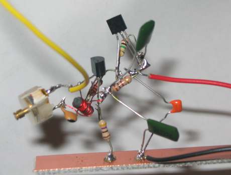
I have been building a Tacho conversion circuit for my RVI current sensing Tacho, to an RVC contact breaker sensing one, so it will work with my electronic ignition. I will add more details here when I can about the project, but here is a little taster 

The circuit board fixed on the Tacho mechanism.

Inside the case:- a little bit tight :?

Not much headroom either :shock:

Perfectly aligned calibration pot over the original calibration hole I don't just throw these things together you know 8)

Calibration in progress
I created Windows .WAV files with square waves to generate pulses, and then fed that signal through my amplifier and then on to the tacho so that the signal was at a level it could see.
The required signal frequencies required for calibration is worked out as follows:
For example, at 2000RPM, (revs per minute as we all know), we get 2000/60 revs per second, which is 33.333 revolutions. For each revolution of the engine only half of the cylinders are firing, so for my V8 I multiply by 4 giving me a calibration frequency of 133.333Hz.
The easy math is to divide the RPM by 15
For simple calibration I injected a 133.333Hz signal for 2000RPM, a 266.666Hz signal for 4000RPM, and a 400Hz signal for 6000RPM.
I managed to calibrate it fairly OK, but the meter was reluctant to reach a reading of 6000RPM. To obtain a reading of 6000RPM, I had to inject a 410Hz signal, which was the equivalent of 6150RPM, so only an error margin of 2.5%
I have added a link to the calibration video below. The screen in the background is the .WAV file generation program I used, and you can see the frequency increasing when the tacho RPM indicator moves 8)
Calibration Video
All good so far
The circuit board fixed on the Tacho mechanism.
Inside the case:- a little bit tight :?
Not much headroom either :shock:
Perfectly aligned calibration pot over the original calibration hole
I don't just throw these things together you know 8)
Calibration in progress
I created Windows .WAV files with square waves to generate pulses, and then fed that signal through my amplifier and then on to the tacho so that the signal was at a level it could see.
The required signal frequencies required for calibration is worked out as follows:
For example, at 2000RPM, (revs per minute as we all know), we get 2000/60 revs per second, which is 33.333 revolutions. For each revolution of the engine only half of the cylinders are firing, so for my V8 I multiply by 4 giving me a calibration frequency of 133.333Hz.
The easy math is to divide the RPM by 15
For simple calibration I injected a 133.333Hz signal for 2000RPM, a 266.666Hz signal for 4000RPM, and a 400Hz signal for 6000RPM.
I managed to calibrate it fairly OK, but the meter was reluctant to reach a reading of 6000RPM. To obtain a reading of 6000RPM, I had to inject a 410Hz signal, which was the equivalent of 6150RPM, so only an error margin of 2.5%
I have added a link to the calibration video below. The screen in the background is the .WAV file generation program I used, and you can see the frequency increasing when the tacho RPM indicator moves 8)
Calibration Video
All good so far