Heavy Duty Front Suspension?

sowen

Active Member
Recently, I've noticed a few mentions in this section (P6 Suspension/Steering) of upgraded front suspension components. Previously I was not aware of any factory or in service upgrades to the front suspension structure and base unit other than the two brackets that weld on either side of the body damper mount.

The first one is sdibbers top link strengthening plate? thread and the picture of the part in question from Kiwirover:

KiwiRover said:
P1090328.jpg

Then in the same thread Quattro mentioned a diagonal brace that goes between the outer pivot of the bellcrank and the top balljoint used in some rally cars.

The next thread, just posted by chrisyork on Springs and Ball Ends has a photo of a front inner wing strengthening kit?

I've refrained from hi-jacking these threads so far, but am too inquisitive to let it be. I'd like to know a bit more about the rally car diagonal brace and the Australian strengthening kit if anyone could provide some details? I think the top link strengthening bracket is covered well enough for me, but I would like to know what thickness steel has been used, and is the outer pivot with the boss cast on the top an early part or specific to foreign markets? In other words, could I find one here in the UK to replicate one?

Are there any more upgrades or modifications done by Rover, or anyone else for that matter for the front suspension structure for more demanding environments :wink: ? The weak points of the rear suspension seem to be either well documented or are obvious to see so as to adapt to reduce any possiblity of failure.

Or am I just being overly curious :LOL:
 
Hello Simon,

On the Australian strengthening kit,...I have never seen one nor have I ever heard it mentioned in discussion.

I have seen a reference to it previously though, hence I can pass that onto you now.

They are available to members of the Australian Rover Owner's Club, which is in Melbourne in the state of Victoria.

http://www.rovercarclubaust.asn.au/

Ron.
 
I just had a quick look at a couple of cars and the top link plate is made from 1/16" (about 1.6mm) steel. Not very thick really. My '70 (s1) TC has the boss on the outer pivot but it isn't drilled or tapped, my '71 (s2) V8 has no boss at all so I suspect you will find it is a series one thing. You will just have to drill and tap it unless you can find one off a '67 or earlier car.
 
Hi Simon

The Australian Kit is also available in the UK from Alan at Classeparts, I organised a free licence from the Austarlian Club for him to licence and sell it. Fitting it requires a lot of work from the basic supplied steel blanks. They need to be "formed" around the shock absorber mount, folded over the underside of the rail etc etc. They also make the assumption that you would not be removing any fittings or existing seams and therefore break the plate at those points. I wouldn't have done that, but it makes it (just) possible to fit with suspension up. Ron is right about the original motivation. Australian roads showed up weakness in the inner wing structure leading to fractures. My interest in it stems from the implication that the inner wing/chassis rail is a bit marginal strength wise, having obvious implications for front suspension bottom link location and hence geometry under very hard driving. There is a consensus that fitting this mod does sharpen up steering feel. I've now driven Lucky around 25 miles since fitting this mod and I think I concur. But I haven't got a direct before and after comparison because rather a lot else happened at the front at the same time. Notably tightening up steering idler mounting (they are known to come loose!), tightening up rollbar location, and sorting out shock absorber location; not to mention getting the springing correct (see my other post). My impression is that the structure of the car at the front feels more solid, in addition to the obvious improvement to the steering response.

The Australian Kit includes a variation on the theme of the "hockey sticks" which were a Rover catalogued mod to the bottom damper mount. These evidently distorted in Police use. The Rover version is a much heavier section but doesn't have nearly as big a plan. It would be possible to fit both. I personally thought the Australian mod looked a better engineered solution and got Colin to fit just that.

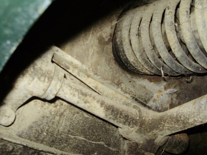
Alan sells two different mods for the lower shock absorber mount. Both address the same issue, which is that the fixing mechanism of compressing the rubber and then securing an end plate by way of a split pin through the mount peg is inadequate for rubber bushes. Also a substantial number of people forget about the initial compression and simply pin through the outer of the two holes, which is provided to locate the Rover service tool. Either way the bottom mount/shock absorber is known to rattle like a good'un after a relatively short time in service. Alan's first mod is a sleeve to fit over the peg and weld in place at the wing end and onto the peg. This sleeve carries a thread at the outer end to allow a more conventional nut to nip the bushes up good and tight. The problem wth this set up is that it needs bespoke and very slender bushes which Alan makes out of nylon rod. I think the reduction in size of the bush is too big a compromise - this with the benefit of hindsight having now got it fitted to Lucky! Alan's other mod is a heavy duty set of bushes to fit the standard pin. instead of being made in two halves to pull in from either side of the damper these are in one piece. I like that. Now I've looked at the options in the metal (or rubber!) I think I would use Alan's HD bushes but go on to thread the outer end of the existing peg so that I could use a Nylok instead of the washer and split pin arrangement.

The rally brace and the stiffener along the bulkhead for the top pivot mounts are one and the same. The idea of the stiffener is to prevent flexing of the outer pivot mount. This mount is the registration for the arm and also carries some of the cornering loads imposed by the top arm, so on the face of it it looks sensible. However the cornering loads are at a distance from the bulkhead and appear there as a moment more than a side to side force. The spacing of the two mounts then reacts in tension and compression to the bulkhead. I therefore think this mod is a false reading of the forces going on in this area and I wouldn't bother with it.

On your car the front inner wings and chassis rail are a bit of an oddity as you have V8 inner wings on a 2000 chassis rail. The Australian mod as supplied won't help you hugely. But the idea is sound. You should have no difficulty replicating it yourself to cover the equivalent areas on your car. Best to give me a ring and I'll talk you through what it does and supply any extra pictures and diagrams you need. (0117 9594766)

Chris
 
Thanks for the replies. I've asked as before I saw the threads I referred to in the original post, the only references of front suspension failure I've read about are of a story in P6 News from a photographer chasing an early p6 rally car, and having a slight car-rock interface moment and bending one of the lower arms, secondly the failure of one of the components on the original v8 circuit racer, and lastly the one I forgot about, the lower damper mounts on the chassis rails.

I agree about the relevance of adding extra bracing to the pivot arm components for cornering forces, as surely the lower arms would take most of the lateral forces, and the pivot arm takes the weight of the car, with limited sideways loading which is well within the scope of the standard suspension set-up. The inner wing strengthening looks interesting, and reading the RCCA site looks to be aimed at the specific requirements of Australian dirt roads while using pas, although some of our post snow pot-holed roads must be nearly as damaging to our cars over here now :LOL:

I have been looking at the front suspension on my car recently, as I will be using minimum 205 width tyres, and currently have a noteable amount of camber to the wheels, and have been thinking about the long term durability of the standard suspension structure when driven hard. I have a set of the brackets that are welded either side of the lower damper mounts ready to fit, and since I cut up my 3500 and looked inside the front chassis rails, I'm less convinced of their effectivity over standard.

I'd assume that the fault with the front damper mounts is that the complete section of the chassis rail twists between the front and rear lower arm mounts causing the fractures described?
 
As I understand it the damper peg distorts the inner wing area and the whole lot fractures away from the chassis leg, BUT I haven't actually seen one or spoken directly to someone who has.

With the Australian kit reinforcement, my interest isn't so much driven by avoiding in service failure - I agree, Simon, that the conditions of use are not comparable - rather it is aimed at making the area close to the lower suspension mounts stiffer. The motivation for the Australian Mod merely demonstrates weakness in that area. That ought to pay dividends in more precise handling. It could even reduce front end shake!

The other mods I have been considering were triggered by seeing the crash test on that Pathe film. There are two clear problems demonstrated, both of which are acknowledged in the section of the workshop manual for the V8 (I haven't read the 4 pot one) for bodyshell checking and repairs. First is that the front bulkhead twists backwards on the cills so that it no longer lies vertically. Second is that the screen pillar/roof rail/B/C post to roof rail joint are clearly not up to modern standard - you can see that the roof rail cripples and allows the top of the screen to move back.

I've not had the opportunity to look at the roof rail screen pillar area yet - hopefully it is a while before Lucky needs his roof off! - but the obvious fisrt step is to seem weld everything in this area. I'd quite like there to be enough space to fit an extra bit of metal alongside the roof rail (and over the top of the screen) between the roof panel and the headlining.

For the bulkhead to floorpan joint things are more obvious - I'd like to add a small box section that wraps around the right angle of this joint and picks up on the inner cill panels a few inches back from the end of the cill and onto the front face of the bulkhead. It would need a bit of careful palying with to ensure it didn't foul the road wheel, but practicable. It would also be nice to do something to brace the transmission tunnel to the bulkhead a little better, but again I haven't had this exposed yet.

Once again the real pay back here isn't in crash resistance, although that would improve, but in shell stiffness. If you know the places where the shell is weak and reinforce them you eventually end up with a much stiffer shell which improves ride and handling.

Chris
 
If you weld up /reinforce areas where the P6 is known to crumple , do you know what would then happen in the event of a crash ?
 
DaveHerns said:
If you weld up /reinforce areas where the P6 is known to crumple , do you know what would then happen in the event of a crash ?
They'd need a new wall on the ol' test rig :LOL:

Sorry, I'll get me coat :oops:

I knew what you meant, honest :wink:
 
Hi Dave

You're quite right to ask that question. At least some mods you could make will alter the crumple performance. The ones I identified above to the bulkhead/floor joint and to the roof/screen rails will actually both improve crash performance. The Australian Mod to the front inner wings could conceivably alter crumple performance in a front ender. My own view is that the P6 is a tad too keen to fold up at the front anyway, so it probably isn't too serious a change.

Do you fancy crash testing a fullly modded one? I'll let you drive!

Chris
 
Chris, you've read my mind on the issues with adding strength to the front inner wings and the possible need to add strength to the shell at the base of the bulkhead at the sill join, and around the screen pillars and roof. I've also seen the Pathe film of the front end crash test at 40mph? into the concrete block, and the infamous scene in Lock Stock And Two Smoking Barrels when Vinnie Jones takes out a Ford Granada at speed!

I have also looked at the transmission tunnel as a possible area that could be modified to help reduce the chances of the bulkhead folding back on the floor, maybe extending it vertically, but again, a fully stripped shell would be required to fully assess the structure of the p6 and any work that could be carried out. Unlike you I've considered these three areas for improving crash performance, rather than shell stiffness. As DaveHerns has mentioned, we're beginning to really go into uncharted territory considering these issues!

You've convinced me on the Australian kit now, but in my mind it really needs to be part of a more significant package as you are all too aware. Something to have a look at in the future I believe :wink: . As for the standard Rover solution, it is probably fine for normal use, but a half-way method between the two maybe adding vertical strengtheners along the chassis rail and up the inner wing, which could if done well, prevent distortion of the inner wing and not significantly affect the crumpleness of the front inner wings. This could either be inside the engine bay, in the wheelarch or both, although one would need to be looking at the car in question and not typing in front of a computer screen to determine what could be done. I think initially I'll fit the reproduced Rover parts I have leaving everything else alone, and assess their performance over time as I go.
 
There was one other observation I forgot to mention. The P6 Gp 2 racer obviously had a roll cage. As well as fixing the front of the cage into the inside of the cills, they also fixed it to the rear of the mounting points for the top link pivot.

Chris
 
Back
Top