Fitting SD1 ignition into a P6B

jp928

Well-Known Member
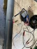
I have an SD1 dizzy etc as in below pic. I have a plan to get the dizzy to fit and pick up the P6B oil pump drive. In exploring if anything else is needed I have some questions. Of the two leads that come out of the separate module, one has a black trace - Coil negative? Other lead - coil positive? The module has a Lucas no 90428B on a white plastic face, lsited as an amplfier. Is this an ignitor?
Oddities - the SD1 manual lists coils for the 4 and 6 cyliner engines (GCL130), but not the V8 models. These list only ignition modules - 32 c5 12 for the Vitesse, 22c 12 for the std engine.
Am I on the right track here? Can I test it off the car with a coil and a 12v source by spinning the dizzy by hand? Are other ignitors like the Bosch BIM024 or any of the many US ignitors relevant to this dizzy?
 

Attachments

  • IMG_0775.JPG
    IMG_0775.JPG
    2 MB · Views: 21
Im surprised too. No response ie.
I went down electronic ign. on my P6b too, but transferred a unit out of a Disco. I had to swap the oil pump gear at the bottom of the distributor from the Disco to a P6b. Had the system in place now for around 10yrs now. Works great !!
 
My dizzy is off a Disco I think also. The document is the first I have found that spells it all out and shows connections. Can I assume that your tacho works ?
 
Next silly question - what is the spec for the screws that hold the vacuum capsule on the body - 5BA? I cant match the thread to any of my thread gauge blades, which would make sense if they are 5BA, tpi of 43.05 !! Are they the same as those that retain the main plate to the body?
 
My dizzy is off a Disco I think also. The document is the first I have found that spells it all out and shows connections. Can I assume that your tacho works ?
Yes my tacho works with the e-ignition
 
I have exactly this setup. WIll post my pictures when I find them.... With GM HEI you can use e-core coils down to 0.3ohms and of course no ballast.
 
Screws - M3.5 works, from a specialist small fastener co. Yes please Peter - pics, part nos, details!
 
If it's any consolation, M3.5 is the thread used for household outlet faceplate screws in the UK. Available at all good suppliers.:)
 
Have my doubts this is true in Oz, but its possible. Will check next time I have to get into a face plate, which is not very likely - most of our faceplates (in my recent experience) clip onto the switch/socket fitting underneath.
 
Coil is just a 1.5ohm one but without the ballast because it's what I have. It's a Taylor cable one as these are nice quality- I tend to buy US made ones as these usually last decades. I have a Vauxhall Astra MKII one which is an e-core coil of around 0.6ohms which is in principle far superior but I haven't fitted it yet. The module is one of these GM parts. The difference being the lucas module is just an electronic switch (i.e.Darlington transistor pair) The GM module does the current regulation as well as the switching and replaces both the points and ballast. Lots of pattern parts available and they all do the same thing. AC Delco or Bosch might give you a quality improvement on some. It needs a heatsink (in my case the metal box it is in which has thermal compound between it and the module). I used shielded microphone cable because that's what I had between the module and the distributor.

1700666711952.png
 
Last edited:
Hi all...
Here's a link to all the info you'll ever need for these ignition modules : General Motors HEI Ignition Modules

I'm running a modified SD1 Vitesse dizzy
1700676672800.png

With the std Lucas module
1700676350238.png

I'll replace the Lucas Module when it fails, with the Intermotor 15210 Ignition Module I have in a box. The important stuff is:
  • Coil positive to the terminal marked ‘B’
  • Coil negative to the terminal marked ‘C’
  • Purple wire from the dizzy to terminal ‘W’
  • Orange wire to the terminal marked ‘G’

Hope that is of some help....
 
Lots of help there, thanks. Exactly what is in the die cast box under the coil? All I have is the dizzy and the small part that was screwed to it - 2 wires in and 2 out to the coil.
 
I finally got all the bits needed for a test - 12v power supply, cheap (A$12) non ballast coil...and wired up as below...it fires nice big sparks - up to around 1/2"! A lazy spin of the dizzy gear, off it goes. Dont you love it when a plan comes together! As the dizzy came off a discovery with a low comp engine (8.13:1) its advance plate was marked 8 - gap to post limiting max advance 4mm, so I cut ~2mm off to allow some more advance for a 9.25:1 CR. Very pleased it was so easy. In fact it will spark with me barely touching the dizzy gear - does that imply the lucas module is fragile, or I need shielded wires from the dizzy to the module? Or something else? A more modern module like the Bosch BIM024?
zn4td1o.jpg


The drive gear has a 3/16" hole for a pin to pickup the P6B oil pump drive - any suggestions as to what sort of pin would be strong enough to be reliable ?
 
Last edited:
Seeing as this was all bench testing, I thought the lack of everything being consistently earthed might be an issue, so I connected the body of the dizzy to the earth/heatsink under the Lucas module.....and the spurious sparks seem to have disappeared.! More progress.
 
The drive gear has a 3/16" hole for a pin to pickup the P6B oil pump drive - any suggestions as to what sort of pin would be strong enough to be reliable ?

The shank of a 3/16" twist drill, it's tool steel but not hardened?
 
A spring pin (roll pin) would be the thing. It self grips the hole stopping it sliding out.
1701081207337.png
 
Back
Top