Fitting a tachometer to a 2000 series 2 auto.

ajcb

Member
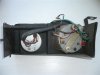
Here we have a negative earth 2000sc series 2 auto and here we have the correct Smiths tachometer with a display of 0-7000 revs per minute.

Now testing the tachometer under the bonnet is just a case of connecting the black earth wire from the tachometer to a decent earth point on the engine, connecting the positive red wire with the white stripe from the tachometer to a nice live terminal such as the live terminal on the starter, connecting the green wire from the tachometer to the low tension circuit between the distributor points and the CB terminal on the coil and then starting the engine.

Fitting the tested tachometer inside the car also seems relatively straightforward in that the black earth wire from the tachometer can be simply connected to the black earth wire from the clock and the positive red wire with the red stripe to the positive red wire from the clock. Great we now have a light in the tachometer! Now we just need to run the green wire from the tachometer in the car to the CB terminal on the coil in the engine bay. OR do we?

Does anyone know if there is an existing wire somewhere nearby in the car that can be used, where it is and what colour it is? Perhaps one is located behind the clock somewhere so little dismantling is required to get to it?

Thanks

Tony Bunting
 
Just fitted mine.

Black wire is negative earth. I think you already have the clock beside, so connect it to the black wire of the clock.

Red/White wire is the positive for the light. Same as black wire connect it to the light of the clock.

Green wire (spade between contacts) is positive for the rev counter. Connect it to the start engine, the positive of the coil... anywhere with tension only when the contact is on.

And now there are two other wires that in fact they are only one (it forms a loop inside the rev counter). You must connect the terminals to the negative of the coil and the dizzy. Find the wire that connects together the negative of the coil and the distributor and connect them in series.

And job done. If the device works a bit erratic swap the connection of these last wires.

Hope this helps.
 
Thanks Shazzbat. I have been away so only just got your message. Will try and find time to fit the techo sometime in September!

Best Wishes

Tony
 
Dear Shazzbat.

I have now had time to digest what you wrote and combine it with what I already know.

It seeems my missing wire, which I believe should be white with a brown stripe, needs to be connected to the single terminal found on its own on the opposite side of the back of the tachometer to the terminals with the green and the black wires attached and the dummy red terminal (see photo). The other end of the missing, white with brown stripe, wire should be connected to the CB terminal on the coil (i.e. the low tension circuit which runs between the coil and the dizzy).

The other end of the existing green wire from the tachometer should be connected to the other side of the coil (i.e. to the low tension wire that goes from the coil to the ignition switch).

Perhaps you would be kind enough to look at the above photo and confirm that the above, and in particular the positioning of the wires on the rear of the tachometer including the missing brown wire with the white stripe, are correct.

Many thanks

Tony Bunting
 

Attachments

  • tachometer.JPG
    tachometer.JPG
    38.2 KB · Views: 2,977
Thanks I will have a look at your link tomorrow.

Ironically I had already come to the conclusion that your tachometer is different and have done some investigation which I was about to put on the forum for you to read when I read your message. My findings are as follows:

My tachometer has RVI on it which means it is current impulse triggered. Smiths later ones, approx post 1973, had RVC on them and are voltage pulse triggered. So mine is definitely the earlier current impulse tachometer. However further investigation on the internet brought up an autocar article which explains that Smiths produced 2 different wiring set ups for their pre 1974 current impulse triggered tachometers. Some have 2 terminals on the opposite side of the rear of the tachometer to the green and black wire terminals but others are like mine with just one terminal. ie 3 terminals in total. It seems that mine has additional internal wiring inside the tachometer and therefore has one less terminal on the back. The purpose of the internal wiring is to take the power from the ignition switch without having a fourth external terminal and wire going to the ignition switch. I think the correct wiring for my tachometer is therefore as follows:

1. Remove the wire which goes from the coil sw terminal to the ignition switch at the coil end and attach it to the green wire on the rear of the tachometer.
2. Then run a wire from the coil sw terminal to the single terminal on the opposite side of the rear of the tachometer to the two terminals with the green and black wires. The tachometer is now connected in series between the coil sw terminal and the ignition switch.
3. Connect the black earth wire from the other terminal on the rear of the tachometer to a suitable earth (same one as the clock).

The tachometer should now work when the ignition switch is turned on and show a reading when the engine is started.

Smiths approx 1974 onwards RVC tachometer is completely different as it works on voltage pulse triggering. Its green wire connects to the sw terminal on the coil which goes to the ignition switch and another wire (the trigger wire) connects from the tachometer to the OB wire on the coil which goes to the low tension terminal on the distributor. I guess this is what you have on your car and that your tachometer has RVC on the face rather than RVI which is on the face of my tachometer.

Does this make sense and do you think I am correct?

Cheers

Tony Bunting
 
We've had a very similar discussion elesewhere about the tacho's for the round dial instrument pack. I must say I didn't realise it also applied to the 4 cylinder strip speedo optional tacho's. This may well explain why a number of people have had such trouble fitting them! Well done Tony!

Chris
 
Thanks Chris and Shazzbat but I have now looked at these pages (see below) and am puzzled. Remember the car is negative earth when looking at the jpeg images of the pages. The last one, smithstacho.jpg referred to by Shazzbat seems to be similar to what I thought. However the first, second,and third jpeg images of pages from the Smiths Care of Instruments Guide seem to contradict the wiring shown in smithstacho.jpg as the Smiths Care of Instruments Guide shows the pulse wires from the RVI negative earth tachometer going to the other side of the coil and to the Dizzy. Or am I missing something? What do you chaps think?


Best Wishes

Tony Bunting
 

Attachments

  • smiths tacho.jpg
    smiths tacho.jpg
    173.2 KB · Views: 2,938
  • smiths document pages 20 to 21.jpg
    smiths document pages 20 to 21.jpg
    189.8 KB · Views: 2,939
  • smiths documentation.jpg
    smiths documentation.jpg
    35.1 KB · Views: 2,939
  • smiths document pages 22 to 23.jpg
    smiths document pages 22 to 23.jpg
    734.8 KB · Views: 2,939
This is going to be from first principles, rather than from knowledge of this particular tacho! First off we need an earth wire to the case of the tacho. That looks like it ought to attach to that terminal at the left of the case, but has actually been wound around the securing bracket instead. Next a power lead to the lamp from somewhere in the instrument light circuit - the red and white one.

Now the difficult bit. We need a power suply to the tacho itself. And we need the loop cable. The loop cable from the negative side of the coil can actually do two jobs - half of the loop cable, plus tacho power supply. There will be a T off inside the tacho housing before the loop detector to bleed power to the tacho which returns via the case earth. The other side of the loop, ie to points interrupted earth on the distributor is then obvious.

So my recipe would be loop cable in and out onto the two main terminals, the black earth cable being positioned there in error. Earth cable to the left terminal and Bob's your uncle. If you get the two loop cables the wrong way round to start with there shouldn't be a problem. The T off for tacho power within the housing will simply be looking at earth instead of power so the tacho won't work and you can swop back to correct. My only doubt is that the left terminal could be insulated from the case, in which case you would need an additional earth connection on to the case as per the current black wire.

What do the rest of you think?

Chris
 
I'll stick to the black diagram on smiths tacho.jpg. That's your device I think, leaving apart that light connections are not shown.

So here we go. I refer now to your device's back.

No problems with light connections, red & white wire plus black wire. Both of them must be connected together with the clock so clock and rev counter have lights when light switch is on. Black wire provides earth to the device as well.

Green wire must be connected to start contact. You can go for the + of the coil instead, since it is easier to find out and with the same result. Any point where you get positive feed only when contact is on would be OK.

And now the main point is coming. Loop wire is missing. You will have to attach that wire to the piece located at the far left of the rev counter case as shown on the diagram below the black .jpg picture. You do not need a special wire (mine is a normal wire used for home electric power), while maybe you will have to take care of the loop's length.

Once you get that wire looped you must connect one end to the negative of the coil and the other end to the distributor. Do not worry about how to connect the ends. Nothing dangerous will happen.

The tacho must work now. If the needle movement is a bit erratic try swapping the ends connections.


My rev counter is almost identical. Only difference is that the loop wire is inside the device and yours is in the outside.

Good luck and regards
 
Shazzbat said:
I'll stick to the black diagram on smiths tacho.jpg. That's your device I think, leaving apart that light connections are not shown.

So here we go. I refer now to your device's back.

No problems with light connections, red & white wire plus black wire. Both of them must be connected together with the clock so clock and rev counter have lights when light switch is on. Black wire provides earth to the device as well.

Green wire must be connected to start contact. You can go for the + of the coil instead, since it is easier to find out and with the same result. Any point where you get positive feed only when contact is on would be OK.

And now the main point is coming. Loop wire is missing. You will have to attach that wire to the piece located at the far left of the rev counter case as shown on the diagram below the black .jpg picture. You do not need a special wire (mine is a normal wire used for home electric power), while maybe you will have to take care of the loop's length.

Once you get that wire looped you must connect one end to the negative of the coil and the other end to the distributor. Do not worry about how to connect the ends. Nothing dangerous will happen.

The tacho must work now. If the needle movement is a bit erratic try swapping the ends connections.

My rev counter is almost identical. Only difference is that the loop wire is inside the device and yours is in the outside.

Good luck and regards

While I agree with most of that, I do have one slight qualm. The + terminal on a series 2 car is fed via a ballast resistor, so I would be a bit sceptical of connecting the green wire to the + on the coil. What we did on our old 2000Auto was to connect the green wire to the +ve supply of the choke warning light, which is ignition switched.

From the smiths tacho.jpg picture of the instructions, the end which to connect to the coil is different from +ve earth and -ve earth cars. ("black marker to ignition coil terminal, red marker to disconnected cable" on negative earth connections), in other words, the direction the current flows in the loop is important.

On our car, there was a white with black tracer wire (or white with grey tracer, or even one end with white & black tracer, the other with white & grey tracer, I cannot recall 100%!) with a bullet connection inside the car. I'm sure this wire was from the coil - terminal to the distributor. We disconnected this, put the male bulleted wire onto the female bullet connector on the tacho, and similarly the female bulleted wire onto the male bullet connector on the tacho. The tacho worked very well.

Of course, the wiring in the same models of Rover P6's can be quite different, especially with different years/periods of build so you would need to exercise some care! If your car has the same wiring as ours did, my feeling is to disconnect the bullet, connect the male bullet onto one end of the loop wire, similarly the female 'mate' of the bullet connector to the other end of the loop wire, (that is, the loop wire is now wired in series with the coil - to distributor) and check if it works. If not, then try reversing the connection.
 
ajcb said:
Thanks Chris and Shazzbat but I have now looked at these pages (see below) and am puzzled. Remember the car is negative earth when looking at the jpeg images of the pages. The last one, smithstacho.jpg referred to by Shazzbat seems to be similar to what I thought. However the first, second,and third jpeg images of pages from the Smiths Care of Instruments Guide seem to contradict the wiring shown in smithstacho.jpg as the Smiths Care of Instruments Guide shows the pulse wires from the RVI negative earth tachometer going to the other side of the coil and to the Dizzy. Or am I missing something? What do you chaps think?


Best Wishes

Tony Bunting

With an RVI tacho, it senses current pulses. The sensing wiring for an RVI can be either between ign switch and the coil + terminal [- terminal for +ve earth cars] , OR, between the coil - terminal [+ terminal for +ve earth cars] to the distributor/points. The current from the switch to the + terminal [- terminal for +ve earth cars] on the coil is the same (well, in theory, and to a very very good approximation in practice! Bound to be some leakage of some sort) as the current from the -ve terminal [+ terminal for +ve earth cars] on the coil to the distributor/points, because they are in series to one another.

I.E. in block diagram and assuming -ve earth:-

IGN Switch ---- RED marked end of loop wire ---- BLACK marked end of loop wire ---- coil + terminal ---- coil - terminal ---- distributor/points.

OR

IGN Switch ---- coil + terminal ---- coil - terminal ---- RED marked end of loop wire ---- BLACK marked end of loop wire ---- distributor/points.

In fact, I think series 1's were between coil - [+ for +ve earth cars] and the distributor, some series 2 TC's and V8's actually between the ign switch and ballast resistor wire to coil +, then Rovers went back to wiring between coil - and the distributor, before changing to RVC. (Voltage sensed), which I think tapped/sniffed the voltage swings on the coil - to distributor wire.

Again, Rover wiring is different on similar models, be careful!
 
[quote="darth sidious" With an RVI tacho, it senses current pulses. The sensing wiring for an RVI can be either between ign switch and the coil + terminal [- terminal for +ve earth cars] , OR, between the coil - terminal [+ terminal for +ve earth cars] to the distributor/points. The current from the switch to the + terminal [- terminal for +ve earth cars] on the coil is the same (well, in theory, and to a very very good approximation in practice! Bound to be some leakage of some sort) as the current from the -ve terminal [+ terminal for +ve earth cars] on the coil to the distributor/points, because they are in series to one another.....................Again, Rover wiring is different on similar models, be careful![/quote]

Thanks Darth. You are correct the series 1 cars (1967) were wired differently. The green wire went to the reverse light switch connection which was activated when the ignition switch is on and gives the positive connection for driving the tachometer. One end of the pulse lead was connected to the existing distributor feed and the other end to the distributor low tension terminal. I think on my 1972 series 2 car it was different in that the pulse lead is connected in series between the ignition switch and the other terminal (sw) on the coil and the green wire taking its positive connection from the ignition switch by connecting it to the same place as the ignition switch end of the pulse lead is connected. I was only confused by the other diagram (in the Smith's maintenance book) which showed the connection on the other side of the coil and the distributor and was not sure I was correct to wire it that way FOR MY PARTICULAR TACHOMETER but now understand from your explanation that the pulses are the same whichever side of the coil the wiring goes for the pulse lead so that problem goes away. Incidentally my tachometer is a RVI 1000/19 GOING TO 7000 RPM. I obviously have to get a pulse lead which I believe does not have to be a special wire and Shazzbat confirms this to be the case.

The only questions remaining are whether the length of the pulse lead matters, what is the best wire to use for the pulse lead and whether there is a problem because the pulse lead has been removed as the Smiths book says it is important it should never be removed. But with regard to the latter Shazzbat removed his as he put a new wire in its place and that works ok.

I still believe that there should be existing wires to connect to near to where the tachometer is positioned rather than running the pulse lead into the engine compartment or disconnecting the, I think white, wire at the ignition switch and connecting there.

Thanks also Shazzbat.

Cheers Tony Bunting
 
No prob!
On ours, I think we had to at least unfasten the speedo and move it to one side to get at the wires behind. I'm sure the white with black wire (from the coil - to distributor) with bullet connection was 'hiding' there. I do remember, it was not as hard a job as we had thought.

But in your case, you have a missing loop wire which is externally fitted, whereas we had one which must have been inside the tacho. In theory, if we had a tacho like yours and found a suitable loop wire (which normal wire may well suffice, as shazzbat has tried), one end of the loop wire would need to go to the male bullet, the other to the female. Which end to which 'gender' of the bullet connection would probably need to be done by trial and error.

I think we used stochlok connectors for the illumination light wire, but I'm not totally sure. I don't really like scotchloks...

But again, you would have to check if your car has a wire similar to what our car did. I know I am repeating myself here, but Rover cars have variations in wiring even on models which are otherwise identical!

Good luck, and please do let us know if you manage to get it to work, and how you did it. Even professional auto-electricians of today have trouble with classic cars, it seems! :shock:
 
I think you worry in excess about different wiring on Series 1 and 2.

In short, it is just a matter of 12 V positive and negative earth for feeding and loop wire for sensing the pulses (assuming that lights wiring is clear enough). Of course assuming as well that you have a coil with +ve and -ve terminals and a dizzy!

I also think that to make up a new wiring is far easier than taking the panel instrument off. Apart from less dangerous.

To get the pulse wires inside the cars is easy through one of the holes you should find beneath the dashboard (or you can drill one). 12 V can be gotten from the fuses case (you would need a multimeter for checking out which wire is OK). You'll get earth from any screw on the dashbord.


On the other hand I have a tacho not used at home. It belongs to an SD series four pots, but the machinery is the same and of course graduated up to 7000 rpm too. It means that you can make up a new tacho by swapping case, screen and needle. The same I did with mine.

Connections are the same as yours whilst with different case. For your information the loop is around half an inch diameter. Never tried but I hope it is still working.

In case your tacho fails I can send it to you by post for free, only post costs (around ten euros from Spain to England).


I am looking forward to know what will happen with your tacho, mate!


Regards
 
Personally, I beg to differ. Surely it's easier (and wiser?) to use the wiring on the car already (as much as possible), and to tap from the ign switched wires behind the dash that supply the choke warning light.

Remember, the series 2 fuse box has issues with regards reliable connections. Personally I'd be sceptical to prod around that area!

Of course, it's Tony's choice! I'm just one younger guy with a reasonable recollection of what we did with ours! Maybe Shazzbat's idea would be overall better than mine! Only actually doing it will answer that question!

Good luck and hope you get it working, Tony!
 
Yes, I agree!! Only actually doing it will answer that question!

Well, the issue is to get it working. At least I think that Tony has the knowledge about connections already. That's the point!

Personally I had any problem with my fuses case (series 2), but anyway it's up to Tony!

The main point is that we are wishing to learn whether that rev counter works or not!


Regards
 
Back
Top