Clock and cut-out

OrganDoctor

New Member
I know this has probably been covered before, but what is the function of the little cut-out device on the rear of the instrument cluster? I don't see it on the wiring diagrams.
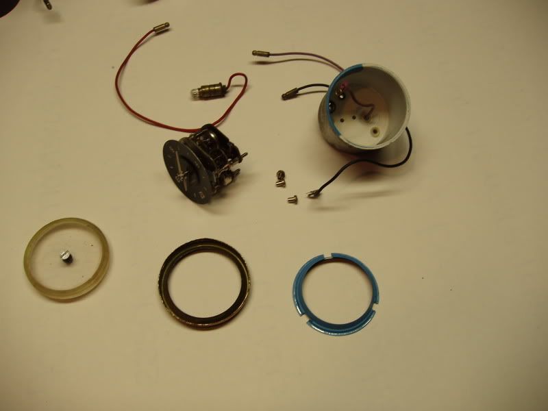
I am now finalizing all the instruments and switches, and one thing I notice is fairly poor ilumination on all the instuments, especially the clock andTachometer. I would like to take the clock apart to fix this situation, but don't see how it comes apart.Anyone done this?
 
The panel illumination comes from little 5w bulbs at the side of the dials which may be blown or just dirty. You can remove the plastic cover from the front of the instrument panel by exposing two screws on each side under the trim.

to get to the screws, first pull off the trim from the side closest to the door, them pull the knobs off the trip meter reset and dimmer switch and remove the side trim panel, then you'll be able to get the screws off and remove the cover to see all the little bulbs.

Something else worth checking is the fuse box as corroded terminals affects the performance of the bulbs.
 
The problem is not with bulbs or connections, but rather in the reflective surfaces within the instuments. These have faded or gone dark with age, and my hope is to go inside and renew them.
Can't see how the clock comes apart without some destruction.
 
Yes you Can !! That is, get the clock apart safely.

Clockwork003.jpg


I am repainting the inside of the shroud and cleaning up the face so that it will be a little brighter under nightime conditions.

Still wondering what that cut-out box is attached to the rear of the speedo casing.......
 
Not sure what you mean by 'cut out box'. There is a small metal box on the back of the speedo that is the voltage regulator for the instruments. It drops the voltage from 12 volts down to about 10 to keep the gauges steady. Is that what you mean? If it works, leave it alone. Generally when these fail, the gauges stop working.
 
I understand, now that you say it feeds the guages. Actually it contains a small wirewound coil which opens normally -closed contacts when it receives enough current.
I am going to check the voltages and see how it actually operates.
A resistor and zener diode would be a more modern fix, should this part fail.
 
OrganDoctor said:
I understand, now that you say it feeds the guages. Actually it contains a small wirewound coil which opens normally -closed contacts when it receives enough current.
I am going to check the voltages and see how it actually operates.
A resistor and zener diode would be a more modern fix, should this part fail.

It basically works by giving an on-off feed of battery voltage. The idea is that the on-off voltage averages out to something like 10V (I think), regardless of actual battery voltage. As the gauges it feeds are themselves slow and sluggish, the on-off action doesn't cause the readings to swing around all over the shop.
 
Now that the clock has been taken apart and restored,I've run it on the bench and see that it is somewhat slow (behind).Don't know how to interpret the + - signs on the back to regulate it.
Which way will speed it up a little? I am assuming it would be in th + direction. Am I right?
 
To regulate the clock, turn the screw on the back from full - to full + and see how far it turns. Then set it exactly to the middle.
If the clock runs slow, then turn the screw towards the + to the 3/4 full position - i.e. half way through the speed up half (I'm not explaining this at all well!!)
Keep going by chopping the zones in half and within a week you'll have your clock running superbly.
 
Back
Top