

Hensen1954
Active Member
Just got a loom, and ECU and new air flow meter.
However, although some of the loom connections are obvious, I have a few that I dont know where they go or what connects to them. Here are the photos of the problem ones.
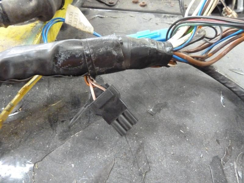
This one is near the ECU...
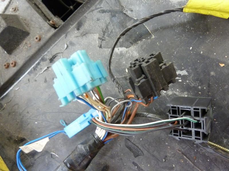
These 3 are very near the ECU.
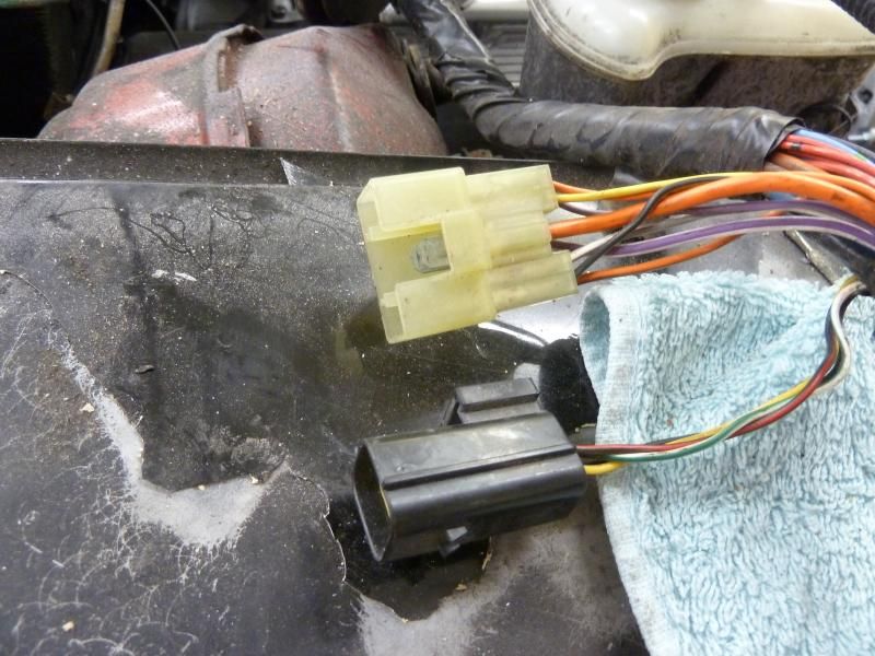
These 2 are between the ECU and where the loom goes through the bulkhead..
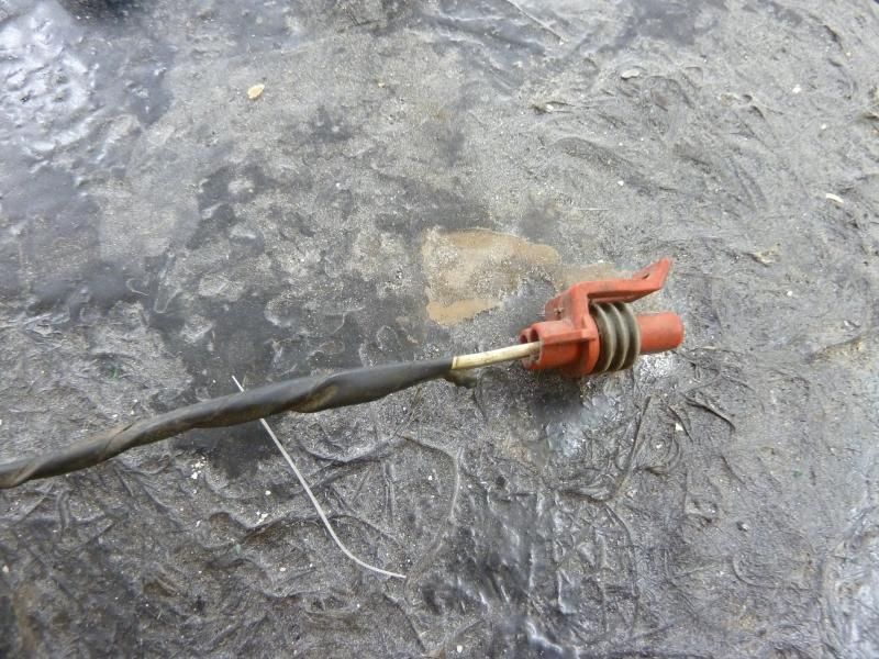
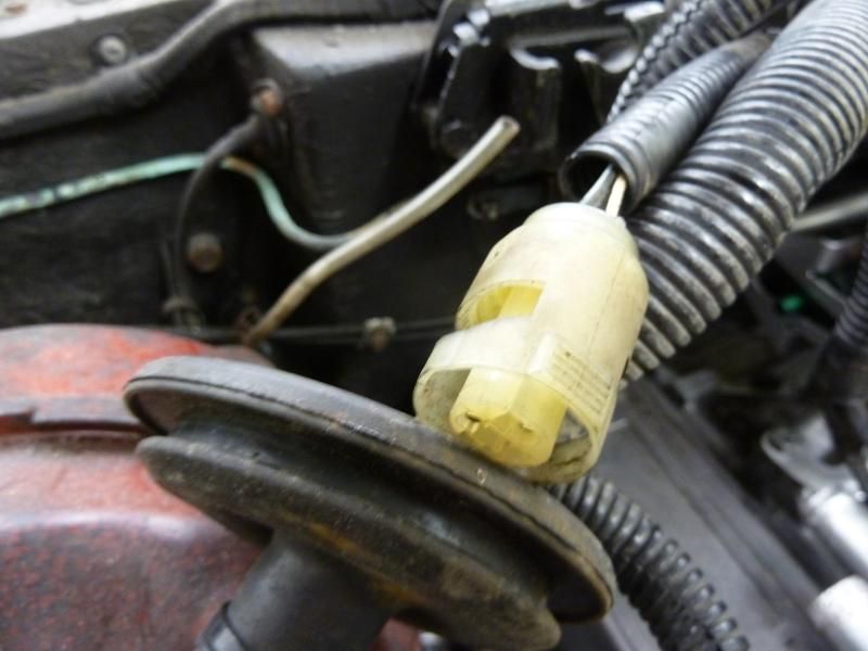
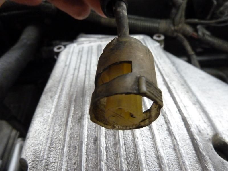
This one is on a long lead that joins the loom on the engine side of the bulkhead..
This one joins the loom at the same junction as the lead that goes to the stepper motor..
This one is further along the loom, close to where the pass side injector wires join the main loom..
This single one is joined to the main lead that goes to the air flow meter..

This is the type of dizzy I have with a 2 pin connection.

Finally, this is the coil as fitted to the car that the 3.9 has been transplanted into.

All help appreciated, need to get this bugger up and running. However, just to cause more problems, when it does start, it might need ECU mods as the block is a genuine 5.0 stroker motor.
However, although some of the loom connections are obvious, I have a few that I dont know where they go or what connects to them. Here are the photos of the problem ones.
This one is near the ECU...

These 3 are very near the ECU.

These 2 are between the ECU and where the loom goes through the bulkhead..

This one is on a long lead that joins the loom on the engine side of the bulkhead..

This one joins the loom at the same junction as the lead that goes to the stepper motor..

This one is further along the loom, close to where the pass side injector wires join the main loom..

This single one is joined to the main lead that goes to the air flow meter..

This is the type of dizzy I have with a 2 pin connection.

Finally, this is the coil as fitted to the car that the 3.9 has been transplanted into.

All help appreciated, need to get this bugger up and running. However, just to cause more problems, when it does start, it might need ECU mods as the block is a genuine 5.0 stroker motor.


