Shazzbat
New Member
Hello all. Just received a rev counter and clock binnacle. I will try to fit it to my car during this Friday, since it is a local holiday here.
Although I think that the wiring layout that's fluttering in my head is correct, I would like someone more used to P6 gives me a hand, just to confirm.
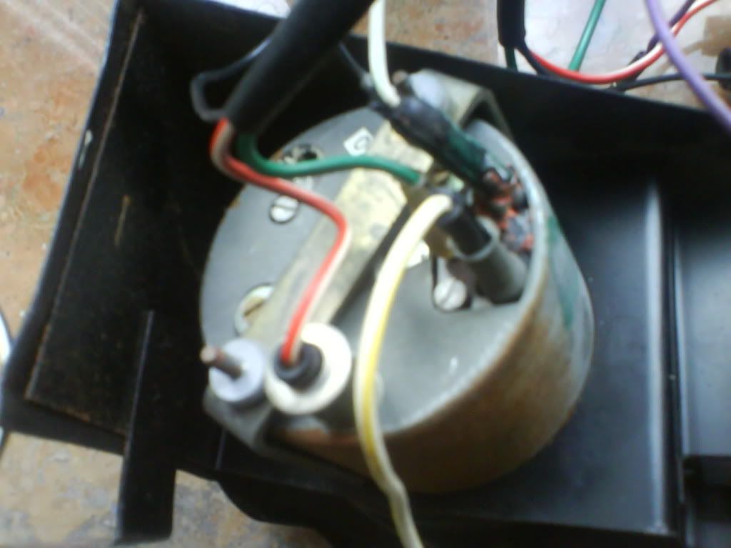
This is the clock's wiring. No problem here, as the connections are the same used currently to the original clock. I realize that lamps and earths are linked together with those coming from the rev counter.
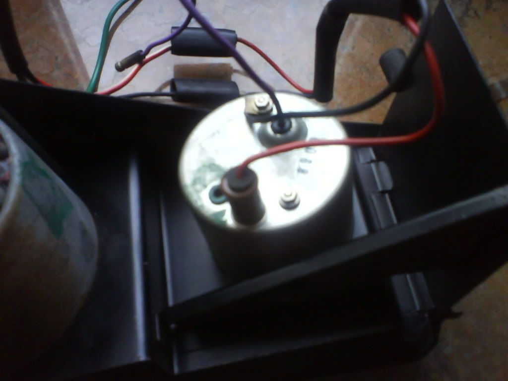
This is the rev counter wiring. Apart from lamp and earth wires, I see three other wires, one white and yellow, one black and white and the green one.
My inspiration says to me that the black and yellow must be connected to the coil, the black and white to the dizzy and the green one to the ignition.
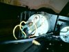
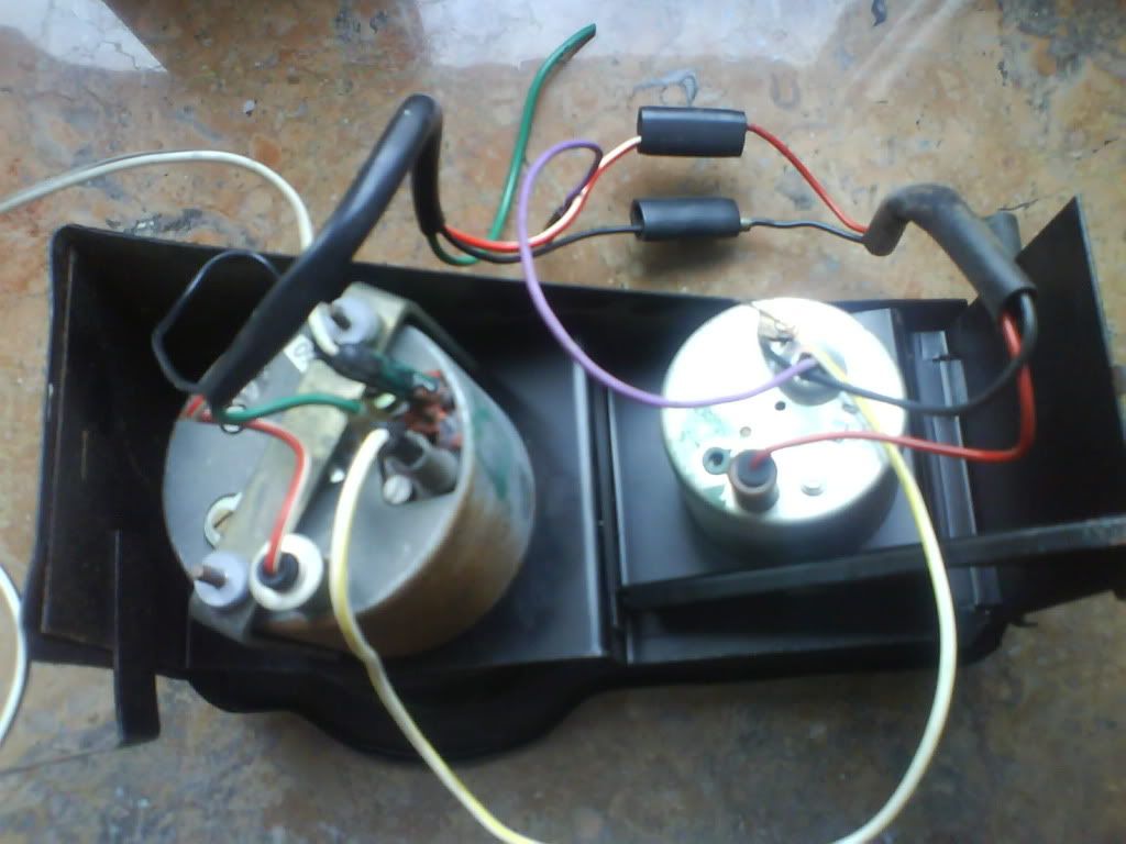
This is the complete sight of the binnacle.
So, please confirm if I am right:
White and yellow to the coil
Black and white to the distributor
Green to the ignition
Black (rev counter + clock). Earth. To be connected to the existing wire for the original clock.
Purple. Clock. To be connected to the existing wire for the original clock.
Red + Red & White (rev counter + clock). Lamps. To be connected to the existing wire for the original clock.
Looking forward to being illuminated by your invaluable knowledge.
Regards
Although I think that the wiring layout that's fluttering in my head is correct, I would like someone more used to P6 gives me a hand, just to confirm.
This is the clock's wiring. No problem here, as the connections are the same used currently to the original clock. I realize that lamps and earths are linked together with those coming from the rev counter.
This is the rev counter wiring. Apart from lamp and earth wires, I see three other wires, one white and yellow, one black and white and the green one.
My inspiration says to me that the black and yellow must be connected to the coil, the black and white to the dizzy and the green one to the ignition.
This is the complete sight of the binnacle.
So, please confirm if I am right:
White and yellow to the coil
Black and white to the distributor
Green to the ignition
Black (rev counter + clock). Earth. To be connected to the existing wire for the original clock.
Purple. Clock. To be connected to the existing wire for the original clock.
Red + Red & White (rev counter + clock). Lamps. To be connected to the existing wire for the original clock.
Looking forward to being illuminated by your invaluable knowledge.
Regards