

You are using an out of date browser. It may not display this or other websites correctly.
You should upgrade or use an alternative browser.
You should upgrade or use an alternative browser.
Sparky's winter/spring/summer/autumn work
- Thread starter quattro
- Start date
unstable load
Well-Known Member
Some of the D-Subs are indeed solder type, but some have crimp type connector pins. Yous looks to me like a solder type, but it's 180 degrees out to tell for sure.As I have started looking at the loom, I am now wondering how the hell to wire this plug? I stripped a wire to test it and the wire is too big to fit the hole. Is it just soldered in? on? am I missing something?
Richard

AeroElectric Connection - Soldering D-Sub Connectors
Connectors ''D'' Type (crimp & solder'' - 098001
Thanks for those links John, they're perfect. Well it's obviously a soldered connector and I'm going to have to give it a go  This is well out of my comfort zone, but I did just buy a building from a company who made computers so they had a lot, and I mean a lot, of electrical equipment, much of which was left in the factory.

I haven't fully considered where the ECU is going to go, so best get that mounted first.
This is well out of my comfort zone, but I did just buy a building from a company who made computers so they had a lot, and I mean a lot, of electrical equipment, much of which was left in the factory. 
I haven't fully considered where the ECU is going to go, so best get that mounted first.
ghce
Well-Known Member
Yep soldered type, easy enough to do but you need a small tipped temperature controlled soldering iron and proper rosin cored solder. I would also buy some heatshrink sleeving so that you can protect each of the new soldered connections from shorting out to adjacent pins.
unstable load
Well-Known Member
Like ghce says, they are pretty easy to do. Tin the iron and apply the heat to the higher part of the terminal with the wire (already tinned and with heatshrink sleeve on) in the socket, when it shows signs of melting the solder tinning, add more and you will see when you have added enough.
Let it cool without disturbing the wire and once cool, slip your pre-installed heat shrink over the socket and shrink it in place.
Depending on application, the backshell may or may not have a strain relief feature to use to secure the wire bundle to in order to prevent yanking the wires out the plug if pressure is applied to the harness.
If you do use the strain relief, remember that the wires on the edges of the plug will end up shorter than the central wires, so take that into acconut when you do the final fit. This is just to neaten the harness and prevent unsightly bunching up of some of the "longer" wires at the plug.
You'll be ok - let the tip heat right up, give it a clean, tin it lightly and then as the chaps above say apply heat and feed a small bit of solder into the connector. Tin the wire and then simply remelt the solder in the connector and push your tinned wire home, apply more solder if necessary. Allow to cool then slide your heatshrink home and shrink it.
Its not hard but it is quite tedious!
Make sure that if you have any plans to use any extra outputs later for things like fan switching etc that you put the wires in now. Its much harder to go back and add them to the loom once you have everything done. Ask me how I know...
Its not hard but it is quite tedious!
Make sure that if you have any plans to use any extra outputs later for things like fan switching etc that you put the wires in now. Its much harder to go back and add them to the loom once you have everything done. Ask me how I know...
Just starting on the loom but am unsure how to keep a working water temperature gauge and rev counter. Anyone know how this is done?
I don't want to make up a loom and then find I should have incorporated some extra wiring for these two items
O/S injector loom - I didn't realise that the full bank of injectors all fire at the same time - doesn't seem right to me?

Nearside

Lambda loom - I need to do this bit first, then fit it underneath the car threaded up into the interior, then fit tank and fuel hoses. Then the car can come back down to floor level and I can start the loom in earnest.

I have found some space under the fuse box on the bulkhead where the ECU fits just snugly, but do these things get hot? I know the land rover boys put them in waterproof boxes so they get no air flow around them at all, but I'm more worried about the (made from wax and chocolate) fuse box. I have been doing quit a bit of research on this and found a megasquirt forum but they have to approve post before they put them on the thread, and they take days!
Richard
I don't want to make up a loom and then find I should have incorporated some extra wiring for these two items
O/S injector loom - I didn't realise that the full bank of injectors all fire at the same time - doesn't seem right to me?
Nearside
Lambda loom - I need to do this bit first, then fit it underneath the car threaded up into the interior, then fit tank and fuel hoses. Then the car can come back down to floor level and I can start the loom in earnest.
I have found some space under the fuse box on the bulkhead where the ECU fits just snugly, but do these things get hot? I know the land rover boys put them in waterproof boxes so they get no air flow around them at all, but I'm more worried about the (made from wax and chocolate) fuse box. I have been doing quit a bit of research on this and found a megasquirt forum but they have to approve post before they put them on the thread, and they take days!
Richard
Hey Richard, looking good there. To answer your questions:
Water temp gauge - the EFI setup (hotwire onwards) has two coolant temp senders/sensors. One is for the ecu and that has the two pin junior timer connector which will be part of your new loom.
The gauge one is closer to the thermostat and uses a single wire. I made up a short 4" lead that converted from the lucar blade on the factory P6 loom over to the small female bullet connector style on the newer sender. This works well enough but the gauge will no longer sit bang on the middle anymore, the resistance curve of the later gauge sender must be slightly different to the P6 one. My gauge is now sits with the needle slightly to the right of centre- you get used to it.
Rev counter is slightly different - there are two ways of doing it. One is to use a few zener diodes connected to the coil pack wiring, and the other is to modify a relay so that acts like a miniature ignition coil to drive your tacho. I went for the second method on the p6. See post 122 in my thread here:
My 3500s project - future daily drive
Basically the tach output from MS is used to ground the relay coil, which generates a flyback pulse like the ignition coil does in a normal car. I ran a wire from the modified relay to the factory P6 wiring where the tach would have been connected to the original ignition coil.
Injector grouping - the factory EFI fires each bank at a time, so called "Batch fire" its not an issue as the fuel basically gets squirted and if the valve is open it gets drawn in and goes bang. If the valve is closed when the injector fires it just has a little longer to vapourise when it boils off the back of the hot valve and then the air:fuel mix waits patiently behind the valve until it opens and draws it in.
Only fully sequential injection is actually timed to valve opening events, and this only works at low rpms to improve emissions slightly. At high rpms, you simply cant squirt all the fuel you need in the miniscule period that the valve is open.
Lastly - I have never noticed any of our MS's get hot. The one on my P6 is in the boot, my Land-rover 90 has it on the rear bulkhead behind the passenger seat, and my Dad's 110 has it in the toolbox under the drivers seat, which is not only small, but lined with sound deadening matting similar to that found under the P6 carpet.
Any questions just let me know! I'm off to take the Red Rocket for its MOT shortly - the first with fuel injection fitted... We'll see what they make of it at the test station!
That's brilliant Quagmire, many thanks for that lot. My build manual say to use the smaller CTS for the ECU as the larger (closer and to the right in this pic) is called a thermontine switch and is not suitable ?

Good luck with the MOT.
Cheers
Richard
Good luck with the MOT.
Cheers
Richard
Last edited:

It passed!
I think your manual may be wrong - the thermotime switch was only on flapper manifolds, used to fire the 9th cold start injector which was on the drivers side of the plenum. From your photos you have a hotwire one the same as mine.
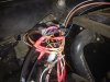
Here's mine- which frankly is embarrassingly mucky and half-arsed looking compared to yours!

The green wire goes off to the factory gauge wiring, and the blue plug is the coolant temp sensor.
Here's mine- which frankly is embarrassingly mucky and half-arsed looking compared to yours!
Working, driveable and MOTed you mean?
Cheers for the help, I'll get that bit done tonight.
Richard
I had a bit of trouble with this bit. The outlet goes into a pipe which controls the fuel pressure regulator, but the ECU needs a vacuum pipe as well. So there is a T Piece in the kit to split the pipe. After a lot of messing about trying to find which outlet to use, I finally found that there should only be one outlet! So do I split one with the T Piece and if so which one? I ended up taking it off again and finding that both just go straight through to the plenum, so I'll be using one each. Easy when you know, highly confusing and time wasting when you don't

Working out a way of mounting the coil packs has taken just far to long, and I must admit to being very glad that I've now done it. The brackets were designed for fitting to a Land Rover and bolt onto the water pump with a small bracket going to the top of the plenum. I drilled a hole into the smaller bracket and bolted it to the manifold. Then made up two brackets and fitted one the a water pump bolt and one to an elongated engine lift bolt.

Cut down the supplied bracket and on it went

On with the coil packs and jobs a good'un

I've managed some of the loom, but more of that later.
Tank is back in, all plumbed up with an 8mm copper pipe running to the engine bay, waiting to be connected to the pump. The bracket has the fuel pump relay and a switch which will cut the power if in an accident. Just waiting for some fuses to arrives and that bit can be wired in,

Richard
Working out a way of mounting the coil packs has taken just far to long, and I must admit to being very glad that I've now done it. The brackets were designed for fitting to a Land Rover and bolt onto the water pump with a small bracket going to the top of the plenum. I drilled a hole into the smaller bracket and bolted it to the manifold. Then made up two brackets and fitted one the a water pump bolt and one to an elongated engine lift bolt.
Cut down the supplied bracket and on it went
On with the coil packs and jobs a good'un
I've managed some of the loom, but more of that later.
Tank is back in, all plumbed up with an 8mm copper pipe running to the engine bay, waiting to be connected to the pump. The bracket has the fuel pump relay and a switch which will cut the power if in an accident. Just waiting for some fuses to arrives and that bit can be wired in,
Richard
Last edited:
The wiring loom(s) are getting there. The injector loom is fitted (not wrapped yet) and the power leads end at the new relay on the N/S wing.

EDIS module hides nicely beside the heater

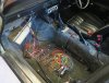
Tin of spaghetti exploded inside the car

Coil wiring ready to fit, but wiring diagram supplied is so confusing that I haven't done it yet This part of the loom runs across to the O/S wing and back to the EDIS (Electronic Distributorless Ignition System) Module.

Richard

EDIS module hides nicely beside the heater
Tin of spaghetti exploded inside the car
Coil wiring ready to fit, but wiring diagram supplied is so confusing that I haven't done it yet
This part of the loom runs across to the O/S wing and back to the EDIS (Electronic Distributorless Ignition System) Module.
Richard
Attachments
Last edited:
Cracking stuff! I saw you had posted on Lr4x4 so knew you were progressing!
Can't got hold of Nige, and was trying to get some clarification on the wiring diagram supplied. It seems (I may be wrong) that '1' on the diagram refers to '3,' '2' to '2' and '3' to '1'
- bit confuzzling.Anyhoo - I am putting my inability to solder down to trying to use a 12W iron and 1mm solder, which apparently isn't a good combination. I also had a solder gun which basically turned the solder into a paste. So after a search around at work I found this

This wiring loom making seems to include a lot of soldering. The injector loom has 16 wires coming from the injectors and these need to go down to 3, although I am leaving it at 5. I stripped the wires level

Twisted them together

Then soldered them - the new kit is a lot better than the old stuff.

Then heatshrink and all's done.

There were 8 power wires from the injectors (Or to the injectors) which had to go to 4, then 2, then 1.
The wiring for the coil packs seems to be as below. I have actually wired them like this now, and wrapped that part of the loom back to the bulkhead, so I hope it's right

Not too far from starting him up now
Last edited:
Right, where do I start
A while ago, I built this little bracket to tidy up the throttle control on the weber. It was bolted onto the engine by some extra long manifold bolts, then the original throttle linkage pushed up, and a rod pushed the throttle open.


Inside you can see some round tubing that I cut to length to act as a support so I could torque the bolts down without any distortion, and the bolt which acts as a pivot. The ‘L’ shape lever sits on a bronze bush and pivots on the unthreaded shank of a bolt which is in turn adjusted for tightness with two nuts on the opposite side of the square section – if that makes sense

I thought I could use this to operate a throttle cable for the EFI unit, but had to make up some extra brackets, and make the square tubing longer (I had some spare so made up a new bit)

Got the bracket from B&Q and just chopped a bit off it, then cut out a 1mm bit of sheet and beat it into shape as a support. Added to the elongated tube it looked ok


Bolted into place using the same bolts, job’s a good’un.

A while ago, I built this little bracket to tidy up the throttle control on the weber. It was bolted onto the engine by some extra long manifold bolts, then the original throttle linkage pushed up, and a rod pushed the throttle open.
Inside you can see some round tubing that I cut to length to act as a support so I could torque the bolts down without any distortion, and the bolt which acts as a pivot. The ‘L’ shape lever sits on a bronze bush and pivots on the unthreaded shank of a bolt which is in turn adjusted for tightness with two nuts on the opposite side of the square section – if that makes sense
I thought I could use this to operate a throttle cable for the EFI unit, but had to make up some extra brackets, and make the square tubing longer (I had some spare so made up a new bit)

Got the bracket from B&Q and just chopped a bit off it, then cut out a 1mm bit of sheet and beat it into shape as a support. Added to the elongated tube it looked ok
Bolted into place using the same bolts, job’s a good’un.
Last edited:
The fuses arrived and I managed to get the wiring fixed. Main power for this fuel pump relay comes from the battery, then it feeds the fuel pump, coil packs and lambda. Fuel pipe is also plumbed in, so the work is finished in the boot area.

The D37 plug was not easy, as the wires I was attaching are actually bigger than the holes they need to fit into. So I decided to cut them into a point so I could at least get some of it located.

Made sure I slid a piece of heatshrink onto all of the wires then started soldering until I started making mistakes, then went indoors. Next day, did some more, until all were done. I don't think I'll ever get a job doing this, but they are all solid and heatshrinked, so shouldn't get any shorts.

.JPG")
The instructions say to twist the wires together on the EDIS and don't fix them properly until the engine runs. Also, don't wrap any of the loom until the engine runs, just in case it doesn't. Not very tidy, but I can tidy it all later.

Engine bay all wired up and ready. I am not happy with the silicone elbow, it just doesn't look right and I really should have measured that air filter, it is a little on the large size.

So, all wired up, petrol in the tank, all fuel pipes connected and secure, charged battery, keys in ignition
It didn't start
The D37 plug was not easy, as the wires I was attaching are actually bigger than the holes they need to fit into. So I decided to cut them into a point so I could at least get some of it located.
Made sure I slid a piece of heatshrink onto all of the wires then started soldering until I started making mistakes, then went indoors. Next day, did some more, until all were done. I don't think I'll ever get a job doing this, but they are all solid and heatshrinked, so shouldn't get any shorts.
The instructions say to twist the wires together on the EDIS and don't fix them properly until the engine runs. Also, don't wrap any of the loom until the engine runs, just in case it doesn't. Not very tidy, but I can tidy it all later.
Engine bay all wired up and ready. I am not happy with the silicone elbow, it just doesn't look right and I really should have measured that air filter, it is a little on the large size.

So, all wired up, petrol in the tank, all fuel pipes connected and secure, charged battery, keys in ignition
It didn't start
Last edited: