302Rover
Member
Hello all,
a number of months ago I joined the Forum and posted a description of my '68 Rover 2000TC which I converted to a 5000TC (my nomenclature) by fitting a Ford 302 V8, a crate motor that I purchased from Ford Racing. Coupled to the Ford V8 is a Tremec 5 speed gearbox to handle the torque output from the 300 hp Ford motor. Anyway the weak link in the drive line has always been the Rover differential. I did help matters a little bit by swapping in a diff from a Rover P6B but that soon began to wear and started vibrating at highway speeds.
A few months ago I stumbled on a local ad for a Jaguar XJS diff, along with the brakes, half shafts, etc, pretty much everything except the mounting cage, all for US$150. "A steal" I thought to myself and drove over to snap it up.
Emboldened by the work that Simon Owen did for his diff swap, and given a very good head start by Simon through a lot of email exchanges, I decided to launch my own swap. Thank you, Simon, for your help. So here are some photos and a description of how I went about it.
Jumping to the conclusion before I even start, I will say that there is no longer any vibration and I can dump the clutch, smoke the tires, and not come even close to harming the bullet proof diff. Or as an Aussie friend of mine says, "Can you give it full leg?" The answer is a resounding 'YES".
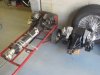
This photo shows the Jag diff, now all cleaned and painted because it was a rusty mess when I got it, next to the Rover diff. As you can see, the Rover diff has the forward pinion extension shaft tube that mounts up front to a cross member. The rear mounts are three bolts in threaded holes in the aft end of the diff. This 3 point suspension was all that Rover needed to maintain position under lateral, axial, and torsional loading. By comparison the Jag diff has no extension shaft housing, and mounts via 4 bolt holes in the top of the diff housing.
I decided to maintain the Rover 3 point mounting scheme, along with the two fail safe rubber mounts in the rear of the car and keep a form of front cross member although I knew that I would need to design a new, stiffer cross member. More on that later.
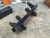
To mount the Jag diff to the rear Rover rubber mounts I built a new mounting structure using a 2 X 2 inch square steel thick wall tube. Two holes were drilled in the ends to pick up the existing Rover mounting bolts, distance pieces, washers, and nuts. I then fashioned a ¼ inch thick steel plate measuring 6 x 6 inches and drilled 4 holes in that plate so it could be bolted to the Jag diff. Note that in the photo the new mount is upside down from what it would be when mounted in the car. The 6 x 6 plate top surface shown in the photo actually interfaces with the top of the Jag diff. (just behind the rear mount is the new front cross member that I designed but more on that later)
Anyway with the square steel tube bolted to the car, I then wrestled the Jag diff in place, carefully locating it to maintain transverse symmetry plus getting it in an acceptable vertical position. Ultimately I needed to have it located so the diff input angle matched the engine/gearbox output angle, yet not have them co-linear. And when the prop shaft was connected, make sure that the prop shaft angle didn’t exceed 3 deg. In the end all this geometry was achieved. But I digressed a bit; what I wanted to describe here was the location of the 6 x 6 steel plate to the 2 x 2 tube. With the diff temporarily located and propped up with a lot of wood bits, jacks, and safety chains, I tack welded the plate to the tube. Out of the car I welded these two pieces together. A problem still to be solved was how to attach the Rover Panhard rod. This I did by salvaging the Rover Panhard rod clevis from the old Rover mount and welding it to the new Jag diff mount.
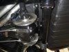
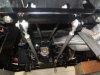
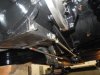
With the new rear mount constructed and bolted in place and the Jag diff bolted in place, I now had to turn attention to emulating the old Rover extension tube housing. This bit of structure would serve to react any torsional movement about the half shaft center line. To do this I decided on using thick wall DOM steel tubing along with chrome moly clevis fittings that I found in a local salvage store for $5 each. To accept these fittings 7/16 thick steel bars, 1.5 inches wide by about 8 inches long were bolted to the lower sides of the Jag diff where there were two convenient threaded holes on each side of the diff. At the top I welded two more 7/16 thk steel bars. You can see these two 7/16 steel bars in the previous photo of the new rear mount. These not only provide clevis attachments but provide added stiffness to the sq tube/steel plate rear mounting structure. Pictures are worth a thousand words so here are two photos showing the forward running tube/clevis arrangements as seen from the rear of the car.
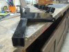
Up front I replaced the Rover cross member with one of my own design and you can see that in this photo. Note that there is no longer any rubber mount here and I worried about noise/vibration/harshness transmission into the car but as it turned out, there was no need to worry. If there is any noise I can’t hear it, partly because my hearing is no longer what it used to be and partly because the exhaust noise is so loud that it drowns out most everything else ;-) The next photo shows the new front cross member. The clevis tabs were located to position the 4 tubes in such a way that they wouldn’t interfere with the prop shaft and the exhaust pipes.
I mentioned exhaust system; one of the pipes was getting too close to the left rear brake caliper and to some suspension components so I took the car to my local muffler shop to have some mods made. These are not shown on any of these photos.
You can also see the big Jag rear brake calipers and rotors. I retained the complete Jag braking system for the rear and have since been tweaking the entire Rover braking system. So far the balance of braking from front to rear seems to be good but I am thinking of doing what Simon did with his project car, namely replacing the Rover front calipers with Jag calipers along with vented Land Rover Defender rotors. But that is another project for another day. Right now I've got an E-Type just patiently waiting for a complete front and rear suspension rebuild.
Finally we need to talk about the prop shaft which bolted directly to the Jag diff but had to be lengthened by about 20 inches. And the two half shafts had to be shortened about ¾ inch each (from memory, may have been a bit more. Like the prop shaft, the Rover half shafts bolted directly to the Jag flanges.
So I think that about covers it. I’m very happy with the Jag diff, which is based on the Dana 44 and is a very popular diff among the hot rodding crowd. These things are bullet proof and I no longer have any worries about stripping gears and dropping bits of shrapnel all over the road. I forgot to mention that the gear ratio is 2.88:1 so the car just loafs along at freeway speeds yet the Ford V8 has plenty of grunt to get off the line fast should that be needed.
Cheers,
Tom
a number of months ago I joined the Forum and posted a description of my '68 Rover 2000TC which I converted to a 5000TC (my nomenclature) by fitting a Ford 302 V8, a crate motor that I purchased from Ford Racing. Coupled to the Ford V8 is a Tremec 5 speed gearbox to handle the torque output from the 300 hp Ford motor. Anyway the weak link in the drive line has always been the Rover differential. I did help matters a little bit by swapping in a diff from a Rover P6B but that soon began to wear and started vibrating at highway speeds.
A few months ago I stumbled on a local ad for a Jaguar XJS diff, along with the brakes, half shafts, etc, pretty much everything except the mounting cage, all for US$150. "A steal" I thought to myself and drove over to snap it up.
Emboldened by the work that Simon Owen did for his diff swap, and given a very good head start by Simon through a lot of email exchanges, I decided to launch my own swap. Thank you, Simon, for your help. So here are some photos and a description of how I went about it.
Jumping to the conclusion before I even start, I will say that there is no longer any vibration and I can dump the clutch, smoke the tires, and not come even close to harming the bullet proof diff. Or as an Aussie friend of mine says, "Can you give it full leg?" The answer is a resounding 'YES".
This photo shows the Jag diff, now all cleaned and painted because it was a rusty mess when I got it, next to the Rover diff. As you can see, the Rover diff has the forward pinion extension shaft tube that mounts up front to a cross member. The rear mounts are three bolts in threaded holes in the aft end of the diff. This 3 point suspension was all that Rover needed to maintain position under lateral, axial, and torsional loading. By comparison the Jag diff has no extension shaft housing, and mounts via 4 bolt holes in the top of the diff housing.
I decided to maintain the Rover 3 point mounting scheme, along with the two fail safe rubber mounts in the rear of the car and keep a form of front cross member although I knew that I would need to design a new, stiffer cross member. More on that later.
To mount the Jag diff to the rear Rover rubber mounts I built a new mounting structure using a 2 X 2 inch square steel thick wall tube. Two holes were drilled in the ends to pick up the existing Rover mounting bolts, distance pieces, washers, and nuts. I then fashioned a ¼ inch thick steel plate measuring 6 x 6 inches and drilled 4 holes in that plate so it could be bolted to the Jag diff. Note that in the photo the new mount is upside down from what it would be when mounted in the car. The 6 x 6 plate top surface shown in the photo actually interfaces with the top of the Jag diff. (just behind the rear mount is the new front cross member that I designed but more on that later)
Anyway with the square steel tube bolted to the car, I then wrestled the Jag diff in place, carefully locating it to maintain transverse symmetry plus getting it in an acceptable vertical position. Ultimately I needed to have it located so the diff input angle matched the engine/gearbox output angle, yet not have them co-linear. And when the prop shaft was connected, make sure that the prop shaft angle didn’t exceed 3 deg. In the end all this geometry was achieved. But I digressed a bit; what I wanted to describe here was the location of the 6 x 6 steel plate to the 2 x 2 tube. With the diff temporarily located and propped up with a lot of wood bits, jacks, and safety chains, I tack welded the plate to the tube. Out of the car I welded these two pieces together. A problem still to be solved was how to attach the Rover Panhard rod. This I did by salvaging the Rover Panhard rod clevis from the old Rover mount and welding it to the new Jag diff mount.
With the new rear mount constructed and bolted in place and the Jag diff bolted in place, I now had to turn attention to emulating the old Rover extension tube housing. This bit of structure would serve to react any torsional movement about the half shaft center line. To do this I decided on using thick wall DOM steel tubing along with chrome moly clevis fittings that I found in a local salvage store for $5 each. To accept these fittings 7/16 thick steel bars, 1.5 inches wide by about 8 inches long were bolted to the lower sides of the Jag diff where there were two convenient threaded holes on each side of the diff. At the top I welded two more 7/16 thk steel bars. You can see these two 7/16 steel bars in the previous photo of the new rear mount. These not only provide clevis attachments but provide added stiffness to the sq tube/steel plate rear mounting structure. Pictures are worth a thousand words so here are two photos showing the forward running tube/clevis arrangements as seen from the rear of the car.
Up front I replaced the Rover cross member with one of my own design and you can see that in this photo. Note that there is no longer any rubber mount here and I worried about noise/vibration/harshness transmission into the car but as it turned out, there was no need to worry. If there is any noise I can’t hear it, partly because my hearing is no longer what it used to be and partly because the exhaust noise is so loud that it drowns out most everything else ;-) The next photo shows the new front cross member. The clevis tabs were located to position the 4 tubes in such a way that they wouldn’t interfere with the prop shaft and the exhaust pipes.
I mentioned exhaust system; one of the pipes was getting too close to the left rear brake caliper and to some suspension components so I took the car to my local muffler shop to have some mods made. These are not shown on any of these photos.
You can also see the big Jag rear brake calipers and rotors. I retained the complete Jag braking system for the rear and have since been tweaking the entire Rover braking system. So far the balance of braking from front to rear seems to be good but I am thinking of doing what Simon did with his project car, namely replacing the Rover front calipers with Jag calipers along with vented Land Rover Defender rotors. But that is another project for another day. Right now I've got an E-Type just patiently waiting for a complete front and rear suspension rebuild.
Finally we need to talk about the prop shaft which bolted directly to the Jag diff but had to be lengthened by about 20 inches. And the two half shafts had to be shortened about ¾ inch each (from memory, may have been a bit more. Like the prop shaft, the Rover half shafts bolted directly to the Jag flanges.
So I think that about covers it. I’m very happy with the Jag diff, which is based on the Dana 44 and is a very popular diff among the hot rodding crowd. These things are bullet proof and I no longer have any worries about stripping gears and dropping bits of shrapnel all over the road. I forgot to mention that the gear ratio is 2.88:1 so the car just loafs along at freeway speeds yet the Ford V8 has plenty of grunt to get off the line fast should that be needed.
Cheers,
Tom
")