Finally a tidy 3500S!

You should mount that whole assembly in a glass case now Tor, it looks too good to use.!!

On the short length of pipe front, I am thinking along the lines of....with a fixed metal pipe with that diameter, you can achieve a radius bend that is far tighter than you could achieve with a flexible hose. So to work the hose would need to be very much longer than the actual distance and the possiblity of contact between the body and the hose would be very real. Also the calipers pivot as the pads wear so a flexible hose could suffer abrasion if in contact with the body. A very much longer hose may also soften the brake pedal which would be a negative.

Ron.
 
SydneyRoverP6B said:
You should mount that whole assembly in a glass case now Tor, it looks too good to use.!!
Thanks for the kind words :D

Dropped the suspension off at the garage to start fitting it very soon. Meanwhile I had a look around to case other work needing doing. Renewing all the seals in the brakes and clutch is on the cards to get rid of the silicone. Reading the Wild Rover thread I am led to believe the clutch master on mine will be from a four-pot, which I'll only know once it's out. I have already got a seals kit for a 3500S so it'd be great to know if I've got it right, in case anyone can tell by the photo.

I'd love to get the brake warning light circuit working as it's supposed to be - ie. correctly wired or near enough - but the fluid pressure breaker on the splitter looks like it was never connected in the first place. The handbrake doesn't work the light but the reservoir senders do.

The alternator has a sticker on it, which is something I've not seen on other cars. Can it indicate that it's a replacement unit?
 

Attachments

  • IMG_1090.jpg
    IMG_1090.jpg
    33.9 KB · Views: 657
  • IMG_1095.jpg
    IMG_1095.jpg
    48.8 KB · Views: 657
  • IMG_1100.jpg
    IMG_1100.jpg
    38.6 KB · Views: 656
  • IMG_1102.jpg
    IMG_1102.jpg
    39 KB · Views: 656
  • IMG_1103.jpg
    IMG_1103.jpg
    53.8 KB · Views: 657
Here's a detail I kinda like - a previous owner has raised the bonnet badge so that it won't trap dirt and moisture and corrode later on. Not sure I'd do that but I'm going to leave it be as you don't notice until you really look.

Badge in good shape, too.

I've said elsewhere that my car has Volvo mirrors (spot the logo), which I initially found bulbous and odd compared to Wingards, but I quickly warmed to them especially as they have a pleasant blue tint and a good-sized surface area.
 

Attachments

  • IMG_1105.jpg
    IMG_1105.jpg
    42.3 KB · Views: 650
  • IMG_1107.jpg
    IMG_1107.jpg
    52.1 KB · Views: 650
  • IMG_1109.jpg
    IMG_1109.jpg
    53.2 KB · Views: 651
  • IMG_1110.jpg
    IMG_1110.jpg
    49.5 KB · Views: 651
I think you will find that the solid pipe is so you have a fitting to allow the flexible to be screwed on. The flexible is screwed in at both ends. This would be a bit difficult to do if you have to screw one end into each caliper!
 
Tor said:
Here's a detail I kinda like - a previous owner has raised the bonnet badge so that it won't trap dirt and moisture and corrode later on. Not sure I'd do that but I'm going to leave it be as you don't notice until you really look.

Hi Tor

I've done the same on mine. Not quite as high but it certainly allows the water to flow cleanly underneath when cleaning the car :D

Dave
 
That is indeed a replacement alternator, Tor. The drains for the heater box are available from Ian, but I'd wait until you do a full heater box out rebuild - surely inevitable sooner or later! The mirrors are in fact on standard Rover Winguard stems and bases, so you can choose what to do whenever you like. The pair of wires from the object close to the servo look like a brake light pressure switch. But this is not the normal one found on a P6 which is a much older type with spade connectors. That implies the T piece in the brake line is non original too. I'd guess the brake system has been completely re-piped at some time? That being the case, it would be interesting to know how your brake lights are triggered. If you are lucky you may well find a mechanical switch operated from a spring attached to the brake pedal? Handbrake switches are known to fail and / or go out of adjustment, so that ought to be a simple fix. The switch is at the rear of the handbrake under the rubber boot. TAke the complete transmission tunnel trim off to access it. I reckon Stan (Vaultsman) or Harvey should know the answer to the clutch slave question! I'd post a separate question about sealing the power steering box properly. A neat idea with the badge!

Chris
 
keynsham1 said:
I think you will find that the solid pipe is so you have a fitting to allow the flexible to be screwed on. The flexible is screwed in at both ends. This would be a bit difficult to do if you have to screw one end into each caliper!

Excellent, never thought of that one, I'd considered the rubbing etc reasons but they could be easily avoided with a supporting bracket to the diff, but of course you can't screw two fittings in at once without removing a caliper, you'd have to have some sort of rotating fitting on the hose, or a small flared extension on the hose (seen these on Peugeot and they're rubbish).

Anyway back to Tor's excellent work.
 
A lot of useful information there, thanks Chris!
chrisyork said:
That is indeed a replacement alternator, Tor.
Interesting! How do I tell which type it is and the Ah rating?
EDIT: I googled LRA103 and found it's an 18 ACR at 43 Ah...
chrisyork said:
The pair of wires from the object close to the servo look like a brake light pressure switch. But this is not the normal one found on a P6 which is a much older type with spade connectors. That implies the T piece in the brake line is non original too. I'd guess the brake system has been completely re-piped at some time?
Well the car was converted to dual-line in 1977, you can see the copper pipes in shot. The splitter and switch arrangement I've seen in every dual-line P6 I've come across here, so it's the right stuff. I have somehow thought the OEM brake light switch was elsewhere and that this was an extra warning feature in case the brake line pressure somehow dropped. :oops: My car has a pedal-mounted switch.
 
Started the refit yesterday, but didn't get very much done. Fitted the crossmember and was putting up the diff hanger only to spot - at a rather late stage I thought - that both upper mounts are completely finished so I've just been on eBay scoring a pair from ianp6man. I spent most of the time setting up the rear brakes the way I hoped they should be, and Harvey just confirmed I got them right in a separate thread. I fitted both pads to the caliper before sliding the disc into place on the locating tabs - owing to the calipers' pivoting facility the discs can be removed/fitted easily even if the pads are set up so close that they actually rub. The pads themselves aren't as restricted as on the front brakes ie. they are free to move about more, making it easier to jam the disc up between them.

With the disc in situ I ratcheted up the calipers by turning the handbrake quadrants (funny looking levers) fully a number of times to bring pads closer to disc. Each full turn gives three soft but audible clicks of the self-adjusting mechanism. After about ten turns it'll get tighter until I no longer hear any clicking and the mechanism feels like it won't tighten further. The idea is that it's now all set. But as Harvey has explained, they're not where they should be. There is still a visible 1+ mm gap between pad and disc to be picked up each time you press the brake pedal or pull up the handbrake (felt as soft or deepish pedal/tall handbrake lever). The rear brakes will engage, but not that well even if I've passed inspection twice for me with the brakes set up as described. The inspector even praised the braking effect of both cars, meaning that the claim that the P6 should stop on its nose when set up correctly is founded on something 8)

The disc must go out before I can ratchet up the mechanism fully. So, I drop the disc and do another two turns (six clicks), slip the disc in onto the tabs. Wobble the inner pad to check for play, try the handbrake quadrant. Less travel, less free play in the pad, out goes the disc again to ratchet up some more. After four or five rounds of this, I was down to turning the quadrant one click before slipping the disc back in. Eventually it was rubbing just a tiny bit. I was unsure if I had overdone it and would need to wind in the piston and start again. Grabbing the disc and jerking it about a bit got the pads to settle and the disc was just free to rotate. Great. Try the quadrant, the pads now engage the disc immediately, and the quadrant only moves up to 1cm when turned by hand - as hard as I can. Before dropping the discs I could turn the quadrant 2/3 of its travel by hand.
 

Attachments

  • bilde 3.JPG
    bilde 3.JPG
    200.4 KB · Views: 570
  • bilde 2.JPG
    bilde 2.JPG
    91.7 KB · Views: 570
  • bilde 1.JPG
    bilde 1.JPG
    71.9 KB · Views: 570
For a couple of weeks progress has been off and on, and I'm reaching a point where somewhat inadequate tools and not having my own garage with pit etc. is making the going a bit frustrating. The car will soon be done for now though. The whole rear suspension has been refitted and now the front is on stands for removal of the rest of the hydraulics and the control lower arms, which will come off tomorrow. Hooking up the handbrake was easy as I left the quadrants to be attached last. Adjusted the cable to bring down the preload to where the quadrants just rest on the stop pin. The cable has a couple of kinks in it but still engages lightly on the first click of the handle. For now I'm happy with that...

To get it all in place I fitted the new diff hanger mounts, but there must be something up with the numbers in the parts catalogue because they're a few mms thinner than what came out. The number is the same as for the front mounting.

Pulled the brake and clutch masters and fitted kits to both of them. They're in good nick, esp the clutch one, being aluminium. The bore was unmarked, but the seals came away like elastic bands and had developed a leak. I have misplaced the kit I bought for it. Whether it's a correct 3500S or a 2000/2200 cylinder I still don't know - I went to the brakes people to ask for a seal only and got a complete kit to fit it off the shelf. I mean, honestly. :shock:

The brake master has been refurbished before, and the plastic bearings put in back to front and in the wrong order. Still, no leak there. The bore has three or four minute pockmarks inside and I've chosen to hone it now and replace it when funds allow.

One annoying discovery today was that the de Dion tube is shedding all its oil through the gaitor. Unsure why it happened now during assembly, but I think it must have compressed too hard when I bolted the halfshafts to the diff while everything was suspended. Or something. All I know is, I renewed the b@$t@rd last summer and just painted the assembly. This time I'll use grease.
 

Attachments

  • IMG_1230.jpg
    IMG_1230.jpg
    111.3 KB · Views: 533
  • IMG_1236.jpg
    IMG_1236.jpg
    66.6 KB · Views: 532
  • IMG_1243.jpg
    IMG_1243.jpg
    126.7 KB · Views: 533
In that photo of the slave cylinder the fluid line appears to have a nasty kink in it, hope you spotted that ?
 
webmaster said:
In that photo of the slave cylinder the fluid line appears to have a nasty kink in it, hope you spotted that ?

^^^WHS^^^

And......How much oil did you put in the De dion when you did it?
 
Tor wrote,...
To get it all in place I fitted the new diff hanger mounts, but there must be something up with the numbers in the parts catalogue because they're a few mms thinner than what came out. The number is the same as for the front mounting.

Hello Tor,

The parts book is correct with the numbers. When the series two cars came about there were from memory something like seventeen changes in the rear suspension/drivetrain. One of which was the introduction of different mounts for the differential mounting plate. The series one cars had all three (diff hanger and pinion) mounts the same, the series two retained the same pinion mount but the diff hanger mounts were totally different. The smaller pinion mounts have been remanufactured and are readily available. These are now used to replace the larger OEM diff hanger mounts on all cars. A shorter bolt which secures the diff mounting plate to the mount is also required to aid ease of fitment.

Ron.
 
webmaster said:
In that photo of the slave cylinder the fluid line appears to have a nasty kink in it, hope you spotted that ?
I have, it does, and I'll get a replacement sorted out for it. Although it lets more than a little fluid through it's quite pinched.
harveyp6 said:
And......How much oil did you put in the De dion when you did it?
Around 0.2 litres :D Not that it seems to have mattered :x
SydneyRoverP6B said:
The smaller pinion mounts have been remanufactured and are readily available. These are now used to replace the larger OEM diff hanger mounts on all cars. A shorter bolt which secures the diff mounting plate to the mount is also required to aid ease of fitment.
Ron that's great, thanks! I'll see about adding a thickish washer at the lower end, maybe some unused seat spacers will do the trick. I replaced both sets of bolts/nuts for the trailing arms and upper links-to-hub using a local supplier, zinc plated in UNF, and they casually charged me a good £40 for the four. In other words, as long as I don't have to I'm not getting any more of them replaced.

The diff hanger seems to have been brought a bit to the right in the past, by adjustment of the panhard rod. I've not yet measured anything, but I had to tug quite hard to get the LHS mounting bolt up through the mount. Didn't need a crowbar or anything though. Maybe it is as it should be, but I'm unsure partly because the old LHS mount was in a worse shape than the RHS one.
 
tor wrote,...
Maybe it is as it should be, but I'm unsure partly because the old LHS mount was in a worse shape than the RHS one.

When I dropped the diff along with the hanger attached back in the 1980s, I don't recall having any problems at all in refitting the bolts through the mounts. Everything lined up perfectly. The L/H mount though does have a much tougher life with mine being replaced twice in total. The R/H mount on the other hand is still the 1974 fitted original, and it remains in excellent condition.

Ron.
 
Only one seal kit to fit now, to the remote, before all the hydraulics are ready to be fitted and bled. The remote had been giving me a 'funny' pedal, which would sink ever so slightly at traffic lights so I had to up the pressure to stay put. I found no fluid in the vacuum chamber but what came out of the cylinder wasn't very pretty. I guess it rarely is. I've honed the bore and it's as good as I'll get it.

Front brake calipers came out fine, pistons left their bores nicely. The first ones came out using a bike pump, the remaining ones were levered out carefully using flat-head screwdrivers at opposing angles. They had very little pitting. Still, I'd have gone for new stainless ones - along with a new remote cylinder - but my budget won't allow it this year and I want the car running, like, now. The RHS one had a squeal, which I think I've sorted now. The pads had some unfamiliar gunk on the back of them, and the anti-squeal shims had a bit of damage to the pin holes. Added to bent pad mounting pins I think I'll have sorted it now that it's all straight and rebuilt using copper grease. Unsure whether I should've greased the pins but I did. And I'm trying to think what would cause them to bend :?
They also got a coat of hot paint.
Brake master got a coat of Hammerite, ready to go in.
 

Attachments

  • IMG_1250.jpg
    IMG_1250.jpg
    53.4 KB · Views: 805
  • IMG_1301.jpg
    IMG_1301.jpg
    68.4 KB · Views: 804
  • IMG_1318.jpg
    IMG_1318.jpg
    69.5 KB · Views: 805
  • IMG_1251.jpg
    IMG_1251.jpg
    54.9 KB · Views: 804
  • IMG_1304.jpg
    IMG_1304.jpg
    53.1 KB · Views: 804
SydneyRoverP6B said:
When I dropped the diff along with the hanger attached back in the 1980s, I don't recall having any problems at all in refitting the bolts through the mounts. Everything lined up perfectly. The L/H mount though does have a much tougher life with mine being replaced twice in total. The R/H mount on the other hand is still the 1974 fitted original, and it remains in excellent condition.
OK that helps Ron. Would it make sense to slacken off the panhard rod a little so that there's equal static loading on the mounts, unless the current D post clearance suggest I leave things alone?

I also pulled the lower control arms for rebushing. Had very little trouble breaking the four tapers, even the lower pillar joints let go nicely. But I had to break the taper on the rear control arm first, and drop the front ones at the body end in order to get proper purchase on the swivel joint with the tool. Will replace the rubber gaitors, which weren't great at all. None of the joints have any discernable play, but the RHS control arm joint moves very freely while the LHS is quite stiff and has a rusting bearing surface. They'll eventually get replaced if I can source them, for now they're soaking in WD40 and will get fresh grease. The bushes were not great; the LHS rear was oil soaked, swollen and separating inside, the RHS rear had dried up, atrophied and completely separated inside.

Fronts were serviceable but on the way out so four new ones went in.

The rest of the front end looks OK, except the dinitrol below the steering box has gone mushy with oil leaks. Upside: There's no rust behind it. Downside: Another item will have to come out when I sort the top link bushes and maybe the heater box. Probably next winter.

Oh, here's my freshly painted remove servo cylinder baking at 120 degrees C. :D
 

Attachments

  • IMG_1248.jpg
    IMG_1248.jpg
    63.8 KB · Views: 799
  • bilde 2.JPG
    bilde 2.JPG
    142.3 KB · Views: 800
  • bilde 1.JPG
    bilde 1.JPG
    107.8 KB · Views: 799
  • IMG_1315.jpg
    IMG_1315.jpg
    57.9 KB · Views: 799
Tor wrote,...
OK that helps Ron. Would it make sense to slacken off the panhard rod a little so that there's equal static loading on the mounts, unless the current D post clearance suggest I leave things alone?

Sounds like a good idea Tor. Otherwise the way I see it, the mount/s will only have their useable life very much reduced.

Ron.
 
The adjustment on the panhard rod is there for one of two purposes. Either to do exactly as you describe - or to centralise the diff in the car. History does not record which. I think I'd start by destressing the mounts, then have a look where the clearance between wheel and D posts have finished up.

Chris
 
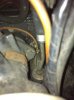
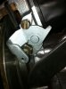
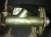
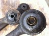
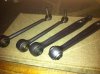
After much procrastinating, turning Four-O, discovering the joys of downhill cycling and being on holiday in the sun, I've finally got some hours spent under the car again. Ball joint boots have been procured, joints cleaned and re-greased, and the control arms have been fitted. I found the easiest way to do them is bush-end first. Then on either side I lined them both up with each other and the upright and knocked the tapers in by hand. It helped to have the steering centered. I've tried fitting them ball joints first with a friend on his car, following his advice, but that was much trickier in terms of lining up the bolt holes with the bushes at the body end. I've clearly not consulted any books here, so I might have kicked in an open door :roll: Split pins had rusted solid in both the rear control arm joints and had to be drilled out.

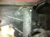
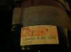
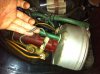
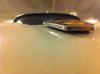
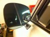
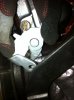
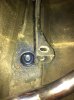
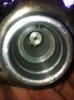
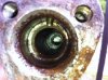
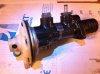
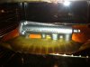
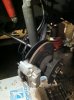
RHF wheel bearing was starting to grind so I got hold of an axle set to go on. Both hubs - the whole of the central cavities - were packed full of grease, and the RHS was missing the non-rotating washer (for lack of correct term) so the hub nut was directly on the outer bearing. Tightening the hub nuts afterwards, the RHS firmed up quicker. Does the missing washer affect this? At any rate, the bearings that came out are probably serviceable, is my guess. Fitted the pair of SD1 hub centre caps in anticipation of the Vitesse rims later on. In the shot you'll see they are an interference fit inside the hub aperture, instead of round the (shiny) outside. Also, the brake rotors both have a fair bit of corrosion on the inside, in patches round the fringe.

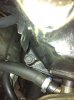
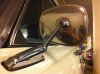
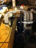
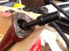
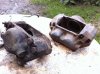
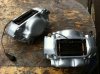
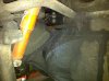
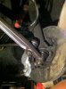
Next came flushing the brake lines. I'm getting rid of the silicone fluid, as mentioned a while ago. I attached an old flexible hose on the wheel end of the lines to direct fluid away from where I didn't want it, and squeezed some water through using a drink bottle with a transmission-oil nipple cap in a bit of hose topside. After a something resembling a brain wave I found the nozzle on the brake cleaner can fit snugly into the lines themselves, so I followed on with alcohol, which evaporates quicker, blew some air through, then attached the new Goodridge hoses and made sure everything in the wheel bays is tidy. Did the same to the clutch line, the union and the master-servo line and closed down for the night. Next come fitting the servo, connecting and adjusting and bleeding everything, and then torquing up the suspension with wheels on the ground. Followed by a late EU inspection 8)
 

Attachments

  • bilde 1.JPG
    bilde 1.JPG
    102.7 KB · Views: 657
  • bilde 2.JPG
    bilde 2.JPG
    91 KB · Views: 657
Back
Top