

The Rovering Member
Well-Known Member
As I mentioned, someone tried to half-inch Fay the aircon before I bought her, mutilating some wiring in the process. The vendors rigged up a switch so I could drive her away, in that process they removed the original switch so in turn I've relieved poor old Poe of hers as a replacement. If you don't make the same mistake as me and take your ignition switch off of your steering lock properly then you won't need this. If you do prise it out & let it spring apart as I did then you may benefit from having a look, but besides that it's a nice little piece of kit befitting a Rover so you might be interested anyway. Basically the switch is a seperate unit mounted on the rear of the steering lock mechanism which facilitates removal & replacement of the unit in case of a fault without having to change the lock mechanism itself. I suppose other vehicles had a similar set-up.
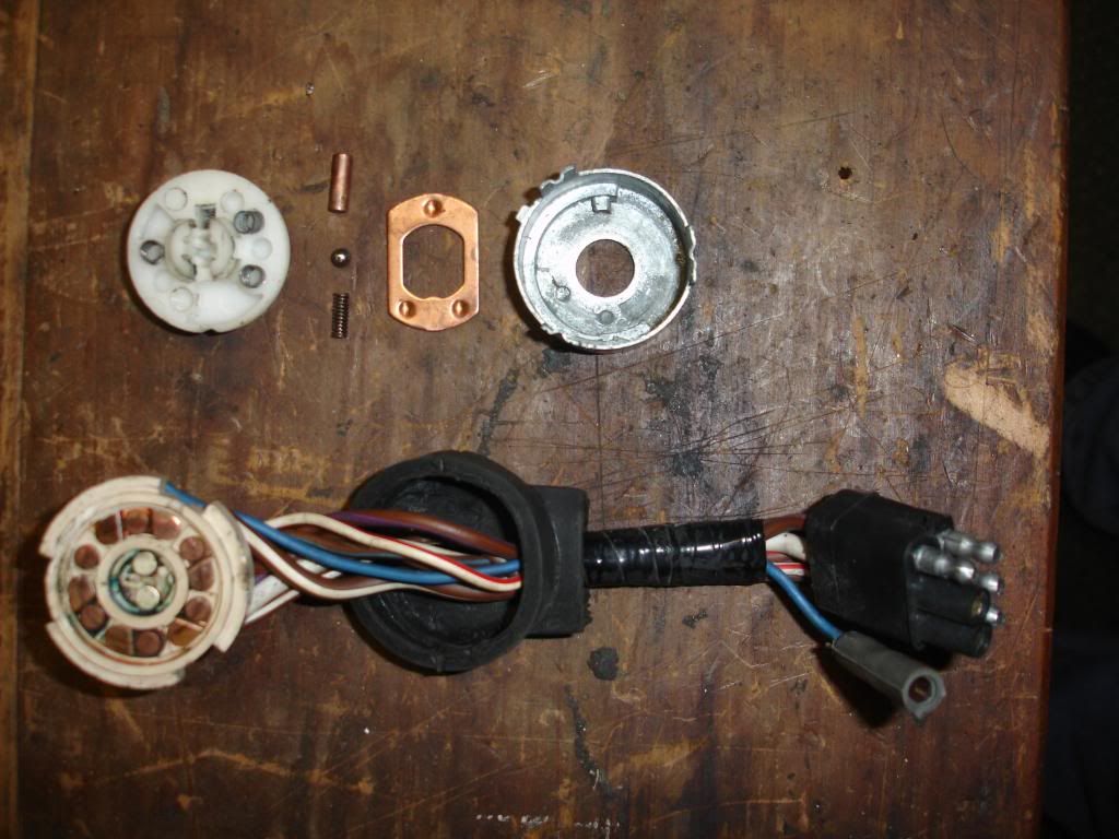
Here are the various bits & pieces:
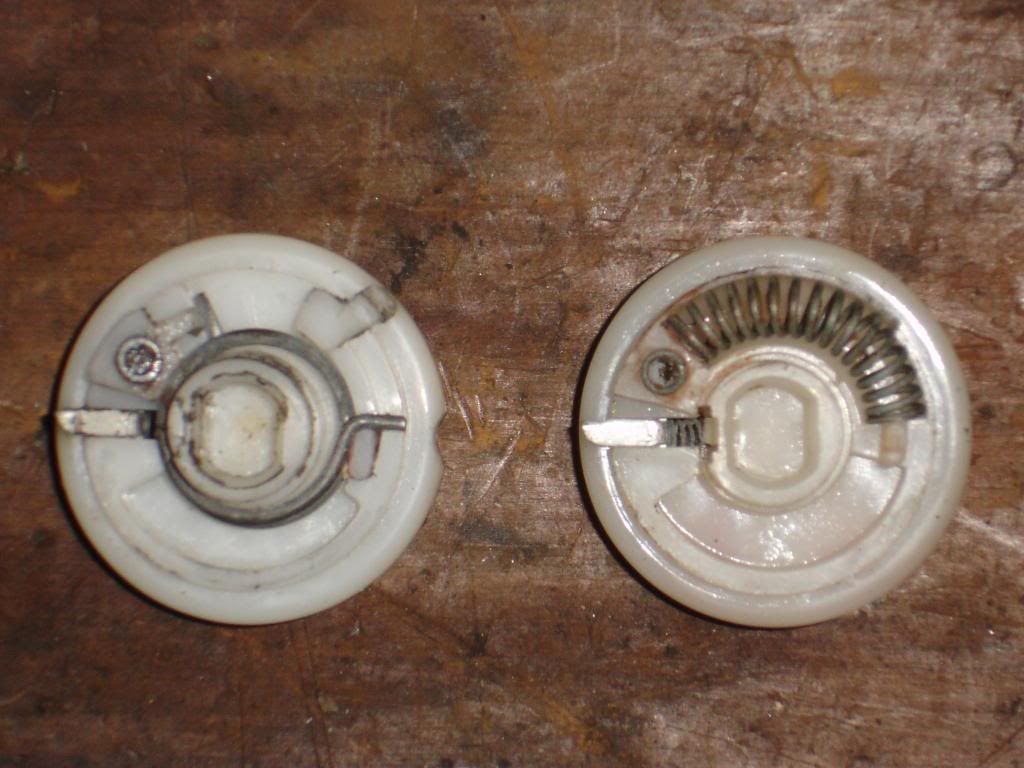
There are two versions of spring mechanism & I happen to have both, the one on the left is the one I'm using (I'm not sure if there should be two springs in the other). The little spring-loaded spike on the left is the thing which stops you turning to the start position twice in a row & you can see the seat for the ball bearing too:
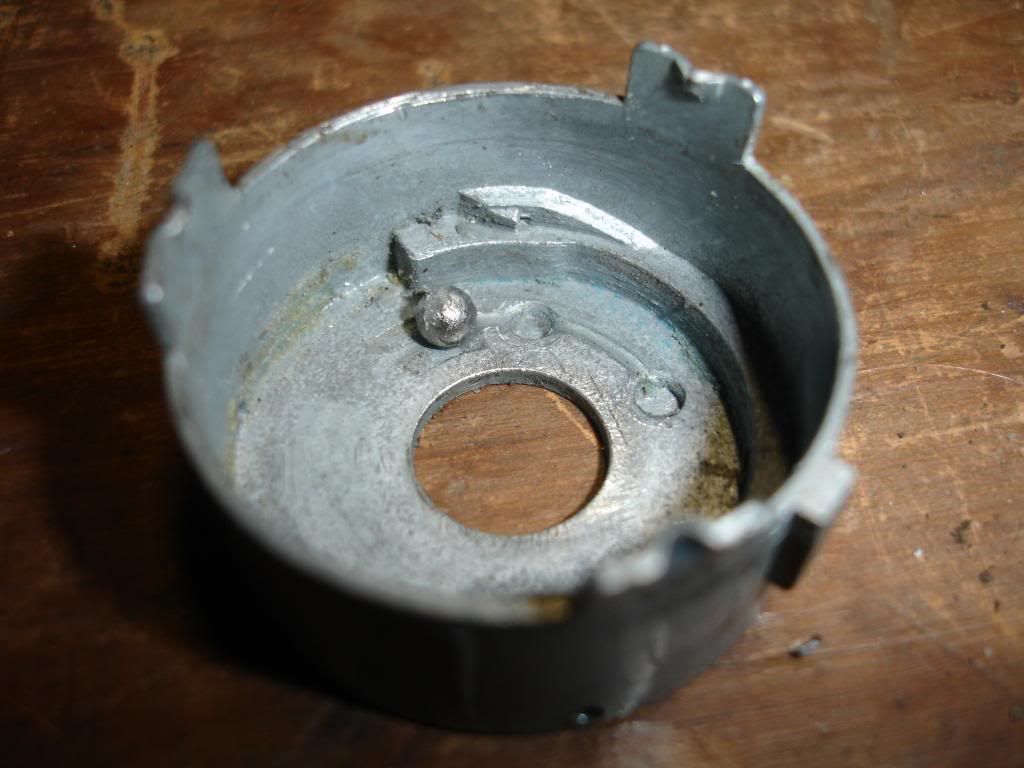
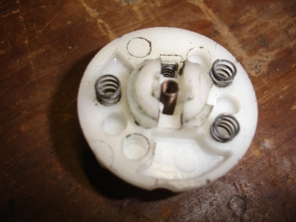
The casing. The ball bearing gives you the nice 'clicky' action. I forgot to put it back the first time I re-assembled so had to take it apart again. You can also see the stop for the one-start system:
The three springs for the plate:
The spring for the bar:
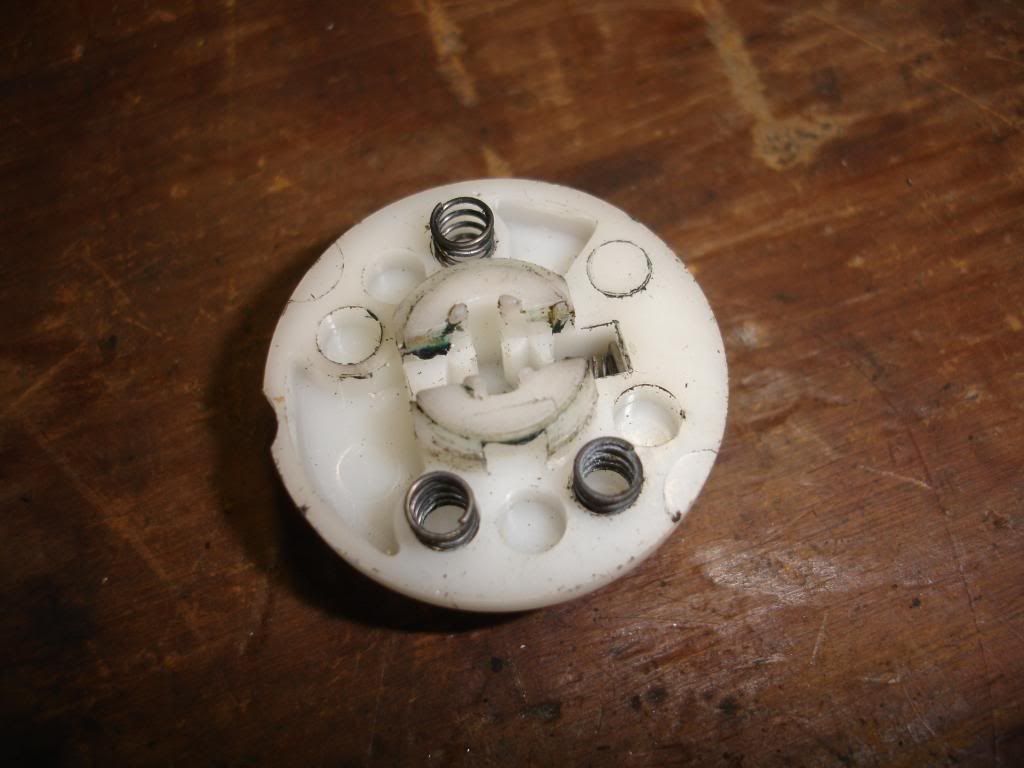
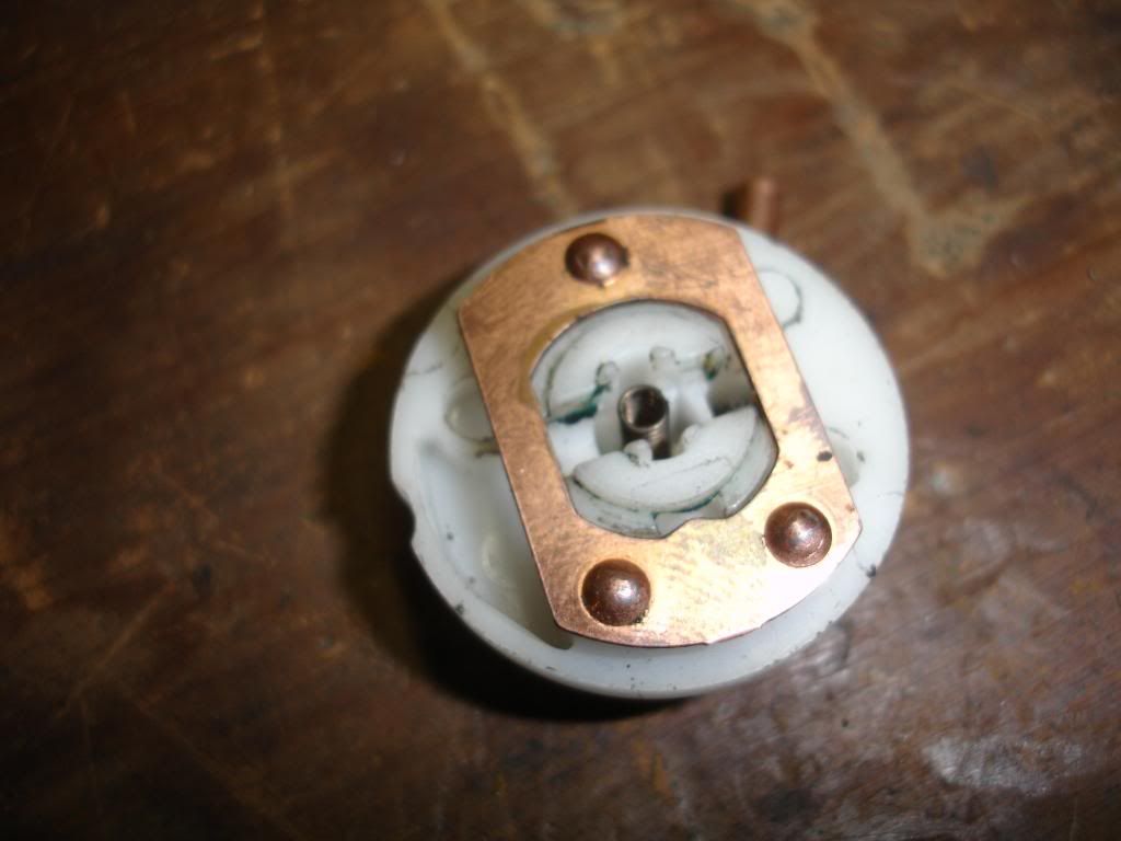
The plate, nodules upward, located by the recess in the plastic mount:
The bar (It took me a minute to realise it went sideways):
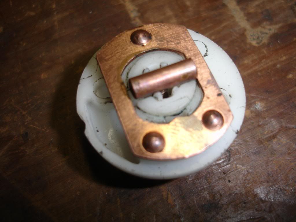
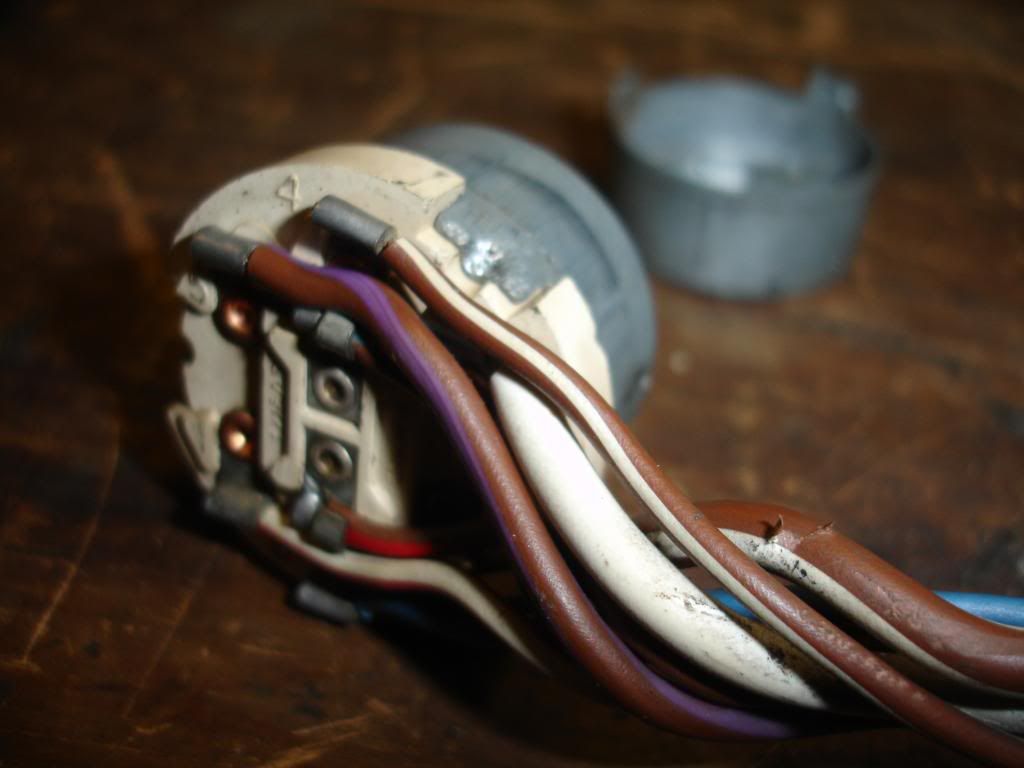
You can see how it will make contact with the two centre pieces. When turned it is lifted slightly to ensure contact is broken:
Hold the ball bearing in the seat with a blob of Vaseline & put the assembly into the casing. There is one large tab to ensure correct alignment. Then squeeze the tabs in & re-point the small indentations, though they're not always there to re-point.
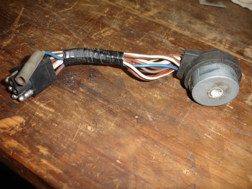
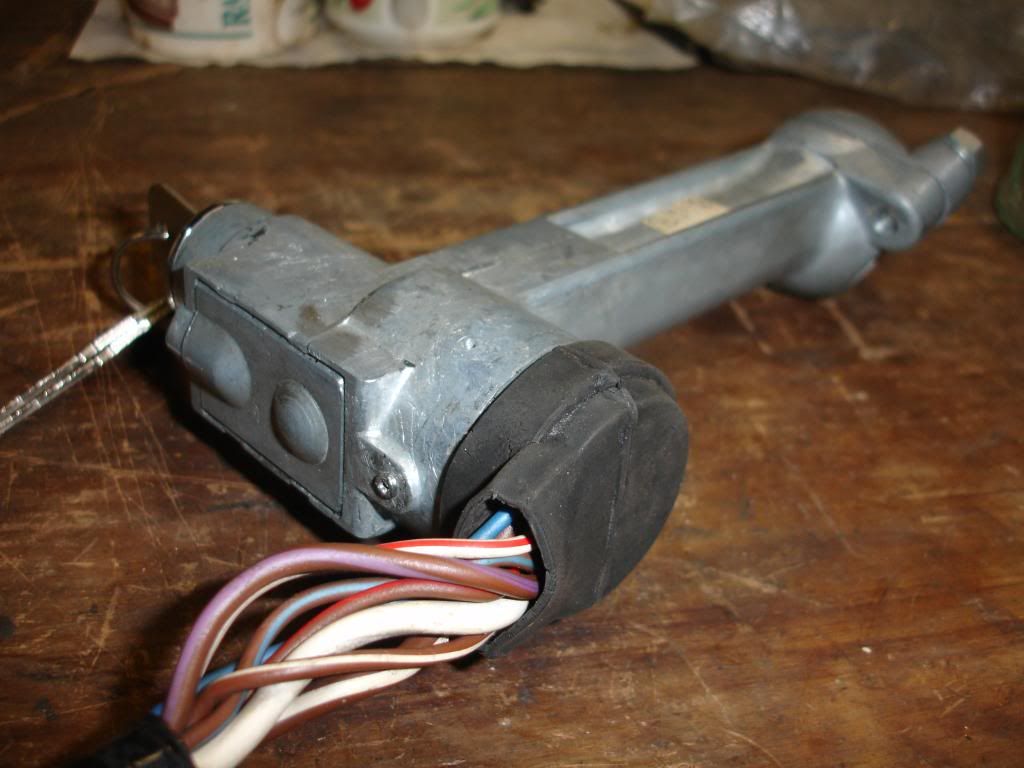
Replace the rubber boot:
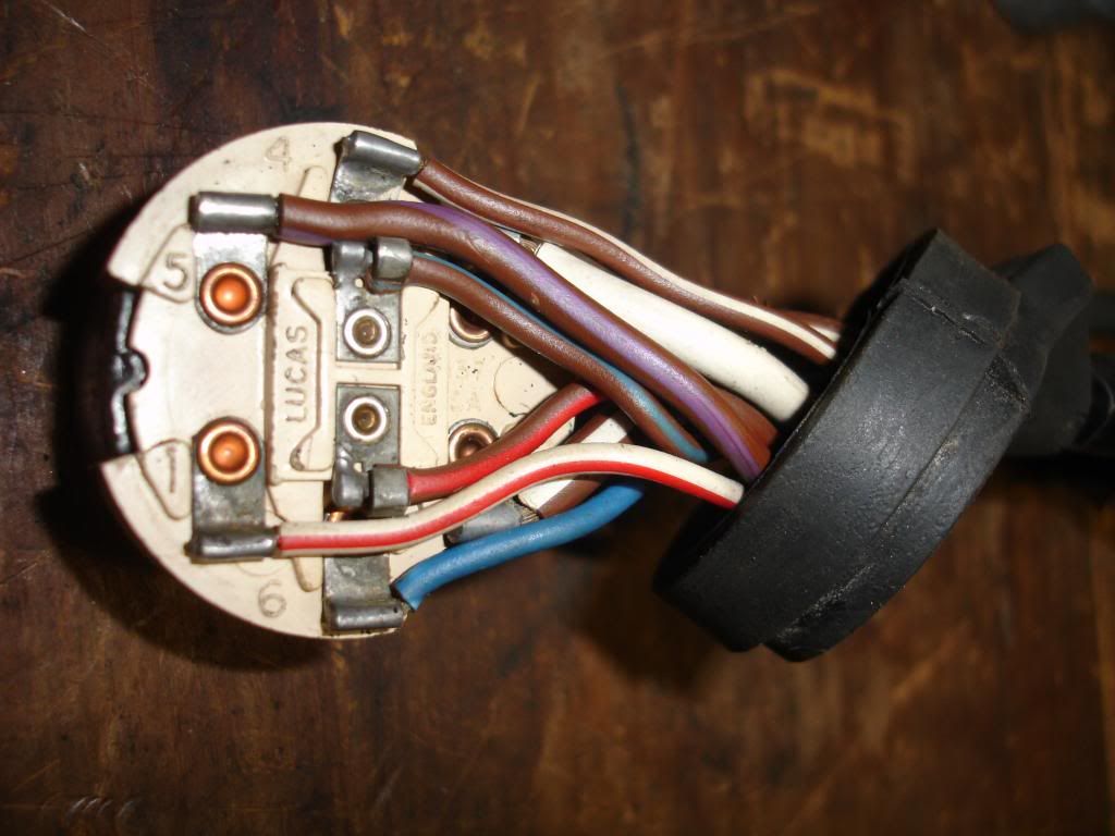
How it looks after re-assembly or if you remove it properly in the first place. The blue wire is for the NADA warning buzzer if you leave the keys in the ignition. (Harvey put his anorak on & looked it up ):
):
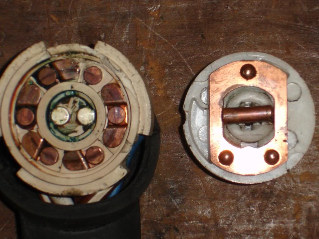
It locates here as you can see. There is a locating peg on the side of the case & a recess on the lock mechanism, again for correct alignment:
The complete assembly. Two very small screws hold the casing in & they can be a b*st*rd to remove too:
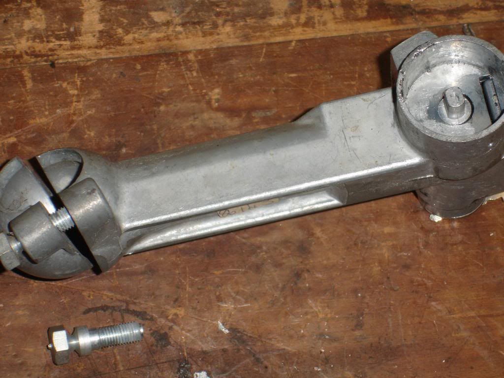
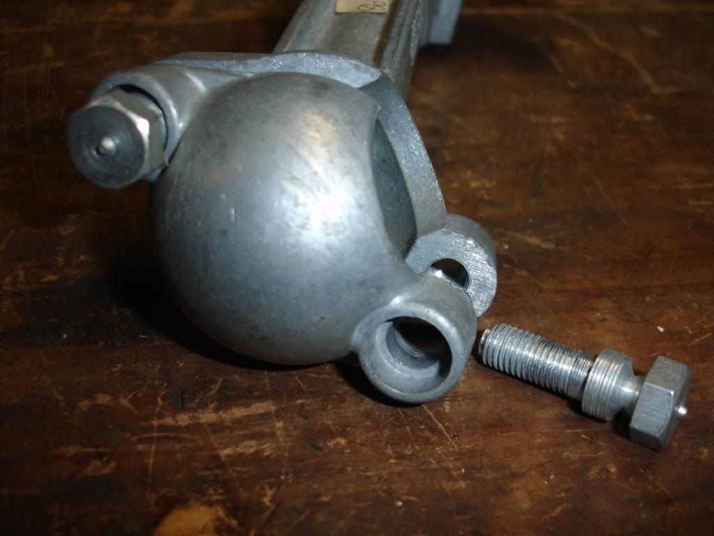
As an aside here are the breaker bolts used to hold the steering lock around the column in case you've never seen them before, this is a new lock I bought from fleabay a few years back though during this operation I discovered it's for a LHD car :roll: :
Here are the various bits & pieces:
There are two versions of spring mechanism & I happen to have both, the one on the left is the one I'm using (I'm not sure if there should be two springs in the other). The little spring-loaded spike on the left is the thing which stops you turning to the start position twice in a row & you can see the seat for the ball bearing too:
The casing. The ball bearing gives you the nice 'clicky' action. I forgot to put it back the first time I re-assembled so had to take it apart again. You can also see the stop for the one-start system:
The three springs for the plate:
The spring for the bar:
The plate, nodules upward, located by the recess in the plastic mount:
The bar (It took me a minute to realise it went sideways):
You can see how it will make contact with the two centre pieces. When turned it is lifted slightly to ensure contact is broken:
Hold the ball bearing in the seat with a blob of Vaseline & put the assembly into the casing. There is one large tab to ensure correct alignment. Then squeeze the tabs in & re-point the small indentations, though they're not always there to re-point.
Replace the rubber boot:
How it looks after re-assembly or if you remove it properly in the first place. The blue wire is for the NADA warning buzzer if you leave the keys in the ignition. (Harvey put his anorak on & looked it up
):
It locates here as you can see. There is a locating peg on the side of the case & a recess on the lock mechanism, again for correct alignment:
The complete assembly. Two very small screws hold the casing in & they can be a b*st*rd to remove too:
As an aside here are the breaker bolts used to hold the steering lock around the column in case you've never seen them before, this is a new lock I bought from fleabay a few years back though during this operation I discovered it's for a LHD car :roll: :